
Wiring device/wallplate installation tool

a technology of installation tool and wiring device, which is applied in the direction of coupling device connection, instrument, and mechanical means, etc., can solve the problems of ganging tool design, difficult and time-consuming for an installer of ganged wiring device, and crooked switches and outlets

Inactive Publication Date: 2008-03-18
GOULD SCHUYLER
View PDF11 Cites 15 Cited by
  • Summary
  • Abstract
  • Description
  • Claims
  • Application Information

AI Technical Summary

Benefits of technology

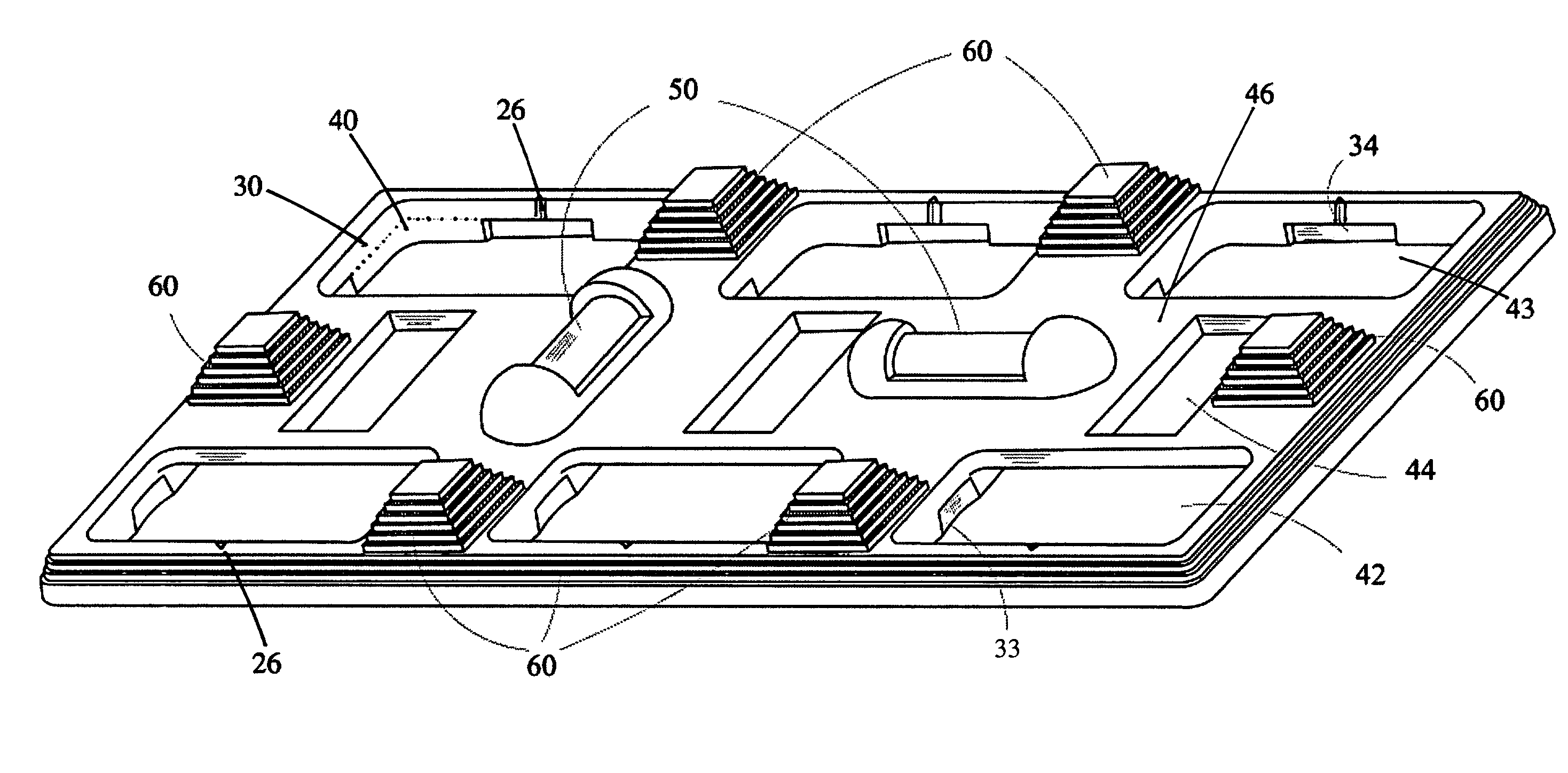
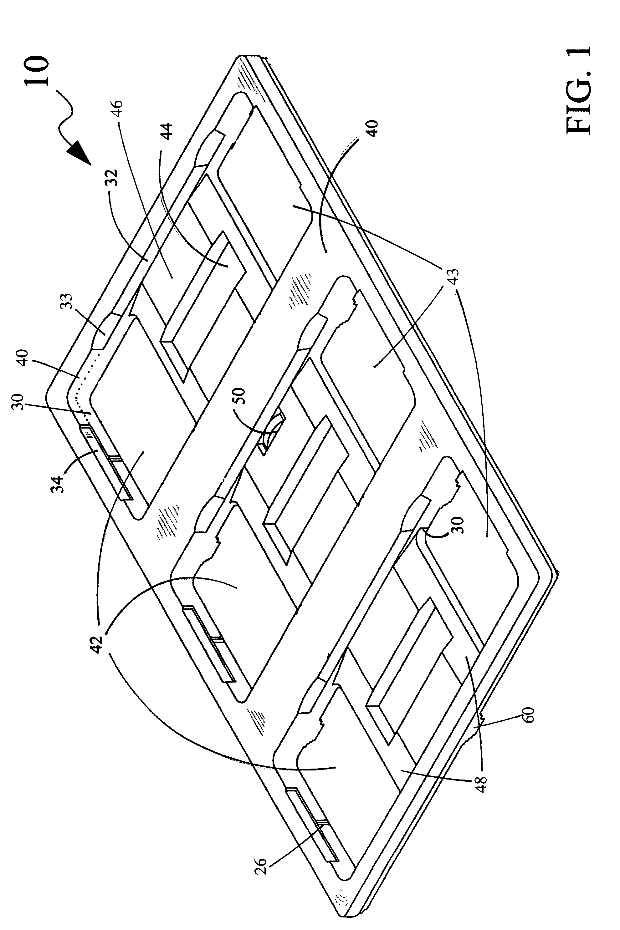
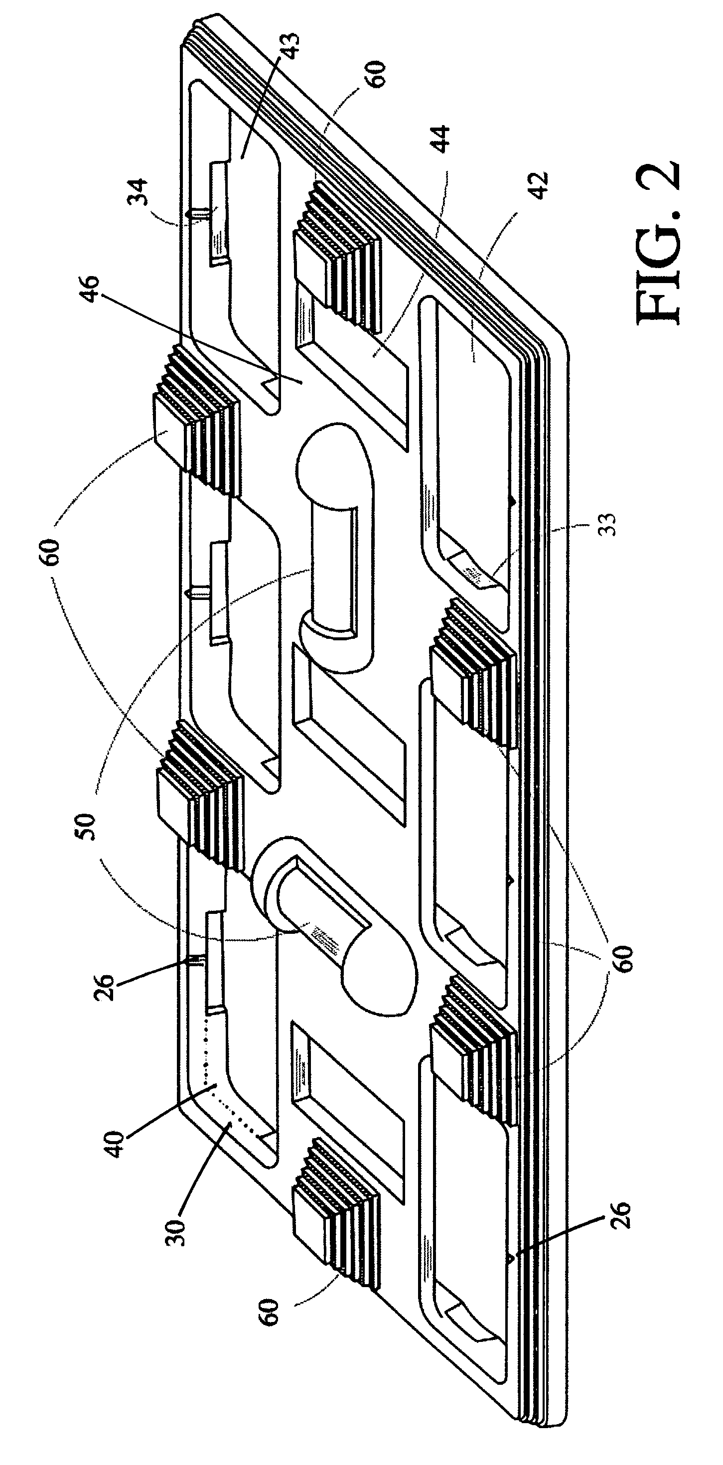
"The present invention provides an improved electrical wiring device installation tool that combines the advantages of prior art tools while overcoming their disadvantages. The tool has a lower and upper overlay with identical openings that align with the device's box and secure it in place. The tool also includes leveling means and gripping means for easy installation. The invention simplifies the process of installing electrical wiring devices in their boxes before installing wallplates."

Problems solved by technology

Generally, without any sort of wiring device installation tool, it is difficult and time consuming for an installer of ganged wiring devices to ensure that each wiring device is truly vertical or horizontal, as the case may be, as well as precisely spaced from and aligned with other wiring devices with which it is ganged so that the faceplate engages all of the wiring devices properly.
Therefore, “crooked” switches and outlets remain a common complaint in the building industry despite varied attempts over the years to solve this installation problem.
This ganging tool has a complex design that hinders the performance of the tool.
It requires a rotatable toggle adapter to position combinations of different types of wiring devices, which makes the device inconvenient to use.
Further, because the adapter engages only half of the margin of a toggle switch, its accuracy is unreliable.
The edge of the tool used to locate the margin of the base of the toggle switch is not a reliable reference point because the margin is not defined by industry standards and varies from manufacturer to manufacturer.
Further, there is no way to incorporate into this device a means to install the newer Decora® (or GFIC) switches and outlets.
Moreover, it requires a user to install removable screws every time the user needs to position a receptacle which makes the tool clumsy to use.
Nor would such a refinement be possible since the webs which hold the toggle switch positioning dowels would forbid the rocker assemblies of Decora® switches from being received into recesses sufficiently deep to engage the margins of the switch and thereby allow the proper positioning of the switch.
The slots in the center of the recesses configured to engage the margins of standard duplex outlets are necessary to receive switch toggles but are so scant in their contours relative to the full contours of toggle switches that they lack significant positioning utility.
The template is limited to adjusting the position of either ganged toggle switches or ganged duplex receptacles.
It cannot be used for ganged combinations of different types of wiring devices.
A further problem with the interface between the two faces is the impracticality of the positioning dowels located for precise registry with the tapped openings in toggle switches which receive the screws used for the mounting of their wall plates.
Further, this template is clumsy and dangerous to carry due to pointed dowel pins that project from one of its surfaces.
All the devices disclosed in the prior art either cannot be adapted to a wide variety of electrical devices available today, are very complex, are not convenient in operation, have limited utility, or are not reliably accurate.

Method used


Image

  • Wiring device/wallplate installation tool
  • Wiring device/wallplate installation tool
  • Wiring device/wallplate installation tool

Examples


Embodiment Construction

[0019]In general, the present invention is a tool for aiding a wiring device installer, e.g., an electrician or homeowner, in installing one or more wiring devices into an electrical box, particularly simplifying the process of orienting each device and / or aligning and spacing two or more devices relative to each other so that a faceplate may be readily installed and the installation is of high quality. The unique design of the present invention allows it to be used with a number of standard wiring devices, including toggle switches, duplex receptacles, rotary switches and rocker switches. An example of rocker switches includes DECORA®. switches manufactured by Leviton Manufacturing Corporation, Little Neck, N.Y. Various ground fault circuit interrupt (GFCI) type receptacles may also be oriented, aligned and / or spaced using the tool of the present invention.

[0020]One utility of the invention is found in each group of recesses / openings formed within the tool that correspond to the va...


PUM


Abstract

Disclosed is an electrical device installation tool configured to aid in spacing, aligning, leveling, and securing, singly or in series electrical device in their boxes before installation on wall plates. The tool comprises a lower overlay with width, length and having at least a first opening configured to substantially conform to engage a portion of one type of electrical device; an upper overlay with width, length and having at least a set of first openings separated by a second opening defining a central bridge, the first and second openings configured to substantially conform to engage a portion of another type of electrical device; a pair of leveling means arranged orthogonally with each other, the leveling means mounted on the tool; and a plurality of gripping means mounted on the tool configured to facilitate a firm and accurate hold on the tool and all its secured electrical devices while in use.

Description

CLAIM OF BENEFIT TO PRIOR APPLICATIONS[0001]This patent application claims the benefit of the earlier-filed U.S. Provisional patent application entitled “Wiring Device / Wallplate Installation Tool”, having Ser. No. 60 / 581,011 and filed on Jun. 17, 2004.FIELD OF THE INVENTION[0002]The present invention relates generally to an installation device, and more particularly, to a system and method of installing electrical wiring devices and their wallplates.BACKGROUND OF THE INVENTION[0003]The electrical industry has essentially standardized components of many types of electrical switch and electrical receptacle systems for everyday residential and light commercial use with conventional electrical power, e.g., 120 VAC 60 Hz power, 240 VAC 60 Hz power, etc. Each of these systems generally comprises an electrical box; one or more wiring devices of various types, e.g., toggle switches, rocker switches, rotary switches, and duplex receptacles, among others; and a wallplate.[0004]Many of these s...

Claims


Application Information

Patent Timeline
Patent Type & Authority Patents(United States)
IPC IPC(8): G01B5/14H01R13/40H02G3/00
CPCH02G3/00Y10S33/10H02G2200/30
Inventor GOULD, SCHUYLER
Owner GOULD SCHUYLER
Learn More