Bender wrench

Inactive Publication Date: 2008-03-18
WARD JESS
33 Cites 45 Cited by

AI-Extracted Technical Summary

Problems solved by technology

While these devices fulfill their respective, particular objectives and re...

Benefits of technology

[0023]Still yet another object of the present invention is to provide a new bender wrench that is easy to use.
[0024]Even ...

Abstract

A bender wrench for removing fasteners from hard to reach places. The bender wrench includes a wrench having a pair of first ends coupled to a plurality of head members that are positionable with respect to the handle. Each of the head members is designed to remove or tighten a fastener without slipping.

Application Domain

Technology Topic

Image

  • Bender wrench
  • Bender wrench
  • Bender wrench

Examples

  • Experimental program(1)

Example

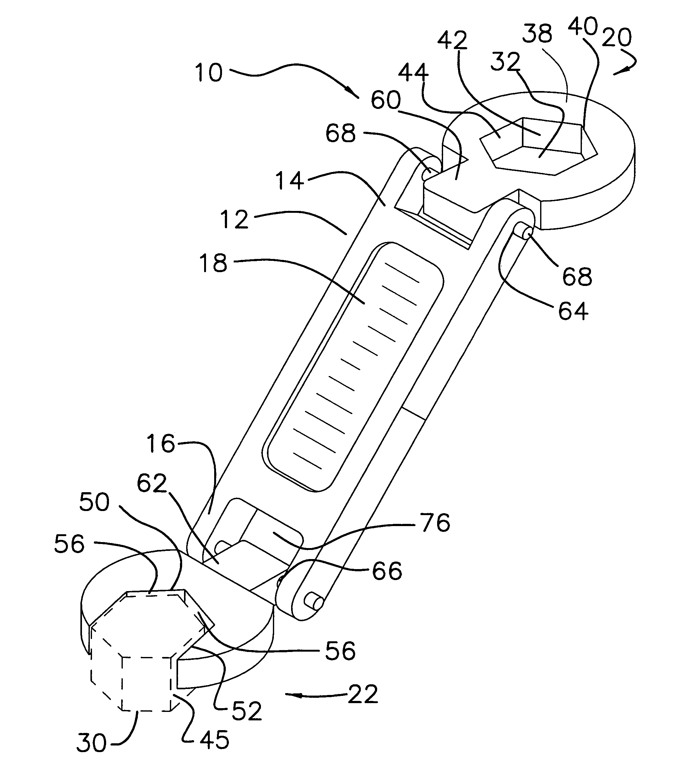
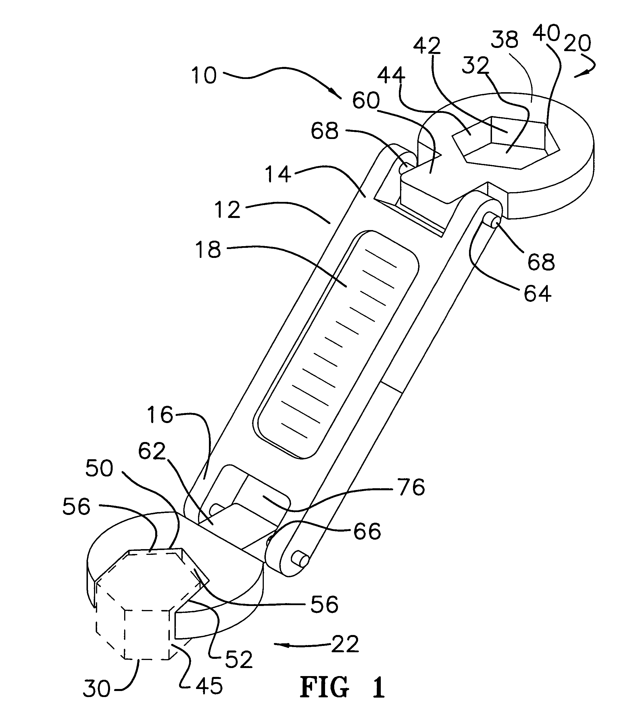
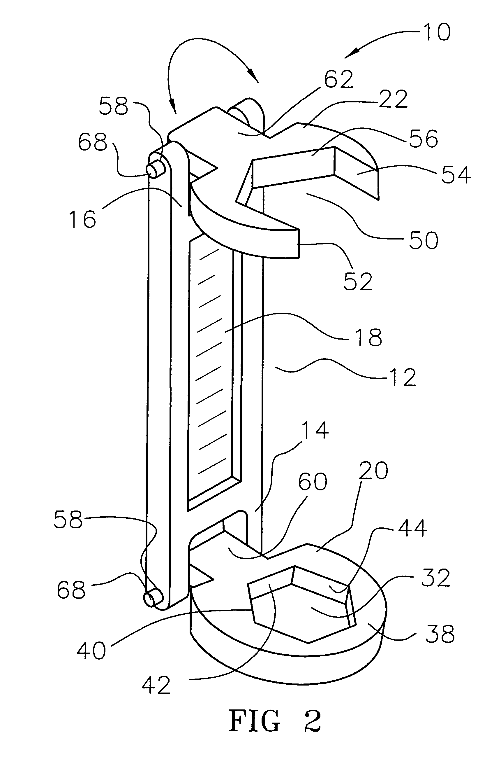
[0030]With reference now to the drawings, and in particular to FIGS. 1 through 3 thereof, a new bender wrench embodying the principles and concepts of the present invention and generally designated by the reference numeral 10 will be described.
[0031]As best illustrated in FIGS. 1 through 3, the bender wrench 10 of the invention is highly suitable for removing fasteners, especially in hard to reach areas. The wrench 10 comprises a body member 12 includes a pair of first ends 14, 16 and a handle portion 18. The handle portion 18 is designed for gripping by a hand of a user. The invention also includes a plurality of head members 20, 22. Each head member of the plurality of head members 20, 22 is pivotally coupled to one of the ends 14, 16 of the body member 12. Each of the head members 20, 22 is designed for selectively coupling to a fastener 30.
[0032]In a significant feature of the invention, each of the head members 20, 22 is positionable at an angle with respect to the body member 12. Each of the head members 20, 22 can be coupled to the fastener 30 to permit rotation and removal of the fastener 30 when the fastener 30 is located in a hard to reach location. At least one of the head members 20, 22 includes an aperture 32 extending between a bottom face 36 and a top face 38 of an associated one of the head members 20. The aperture 32 is designed for receiving the fastener 30. Each of the head members 20, 22 is designed for rotating the fastener 30 when the body member 12 is rotated around the fastener 30. The aperture 32 of the associated one of the head members 20 includes a perimeter wall 40. The perimeter wall 40 includes a plurality of faces 42, 44 that define the aperture, each of the faces 42, 44 of the perimeter wall 40 is designed for abutting one of a plurality of surfaces of the fastener 30 such that the faces engage the faces of a fastener for preventing the head member 20 from slipping around the fastener 30.
[0033]At least one of the head members 22 includes a cut out 50 extending inwardly from a front face 46 of the head member 22. The cut out 50 is designed for receiving the fastener 30. Each of the head members 20, 22 is designed for rotating the fastener 30 when the body member 12 is rotated around the fastener 30. The cut out 50 of the associated one of the head members 22 includes a peripheral wall 52. The peripheral wall 52 includes a plurality of abutment walls 54, 56 defining the cut out 50. Each of the abutment walls 54, 56 of the perimeter wall 52 is designed for abutting one of a plurality of surfaces of the fastener 30 such that the abutment walls 54, 56 are for preventing the associated one of the head members 22 from slipping around the fastener 30.
[0034]Each of the head members 20, 22 includes a shank 60, 62. The shank 60, 62 of each of the head members 20, 22 includes a bore 64, 66 that extends through the shank 60, 62. Each of the ends 14, 16 of the body member 12 includes a channel 74, 76. The channel 74 of one of the ends 14 of the body member 12 receives the shank 60 of one of the head members 20 such that a pair of pin apertures 58 of the body member 12 are aligned with the bore 64 of the shank 60 of an associated one of the head members 20.
[0035]A pin 68 is removably insertable through each one of the pin apertures 58 of the body member 12 and the bore 64 of the shank 60 of the associated one of the head members 20. The shank 60 of the associated one of the head members 20 is inserted into the channel 74 of one of the ends 14 of the body member 12 such that the pin 68 permits the head member 20 to pivot with respect to the body member 12. Each of the pins 68 has a first end that is capable of moving through the pin apertures 58 of the body member 12 and through the bore 64 of the shank 60 of the associated one of the head members 20. Each of the pins 68 has a second end that is enlarged in size such that the second end is incapable of moving through the pin apertures 58 of the body member 12 and through the bore 64 of the shank 60 of the associated one of the head members 20.
[0036]In use, the hand of the user grips the handle of the bender wrench and selectively places the aperture over the fastener turning the wrench clockwise to tighten or counter-clockwise to loosen the fastener.
[0037]With respect to the above description then, it is to be realized that the optimum dimensional relationships for the parts of the invention, to include variations in size, materials, shape, form, function and manner of operation, assembly and use, are deemed readily apparent and obvious to one skilled in the art in view of the foregoing disclosure, and all equivalent relationships to those illustrated in the drawings and described in the specification are intended to be encompassed by the present invention.
[0038]Therefore, the foregoing is considered as illustrative only of the principles of the invention. Further, since numerous modifications and changes will readily occur to those skilled in the art, it is not desired to limit the invention to the exact construction and operation shown and described, and accordingly, all suitable modifications and equivalents may be resorted to, falling within the scope of the invention.

PUM

no PUM

Description & Claims & Application Information

We can also present the details of the Description, Claims and Application information to help users get a comprehensive understanding of the technical details of the patent, such as background art, summary of invention, brief description of drawings, description of embodiments, and other original content. On the other hand, users can also determine the specific scope of protection of the technology through the list of claims; as well as understand the changes in the life cycle of the technology with the presentation of the patent timeline. Login to view more.

Similar technology patents

State-based system for automated shading

InactiveUS7941245B1Easy to useMinimize inconvenienceSampled-variable control systemsBurglar alarm by openingState of the EnvironmentState specific
Owner:POPAT PRADEEP PRANJIVAN

Adaptive canceller for frequency reuse systems

ActiveUS6859641B2Effective and efficient mannerEasy to useRadio transmissionTransmission noise suppressionSignal of interestSatellite
Owner:RAYTHEON APPLIED SIGNAL TECH

Reconfigurable measurement system utilizing a programmable hardware element and fixed hardware resources

InactiveUS20030163298A1Easy to useSimplyError detection/correctionMeasurement arrangements for variableProgrammable hardwareComputer hardware
Owner:NATIONAL INSTRUMENTS

Classification and recommendation of technical efficacy words

  • Easily understood
  • Easy to use

Selective writing assessment with tutoring

ActiveUS20070238084A1Easily understoodElectrical appliancesTeaching apparatusAssessment evaluationSoftware engine
Owner:VANTAGE TECH KNOWLEDGE ASSESSMENT

Laser assisted total joint arthroplasty

InactiveUS20090234360A1Easy to useNon-surgical orthopedic devicesSurgical sawsLaser assistedLaser guidance
Owner:ALEXANDER VLADIMIR

System, method, and apparatus for settlement for participation in an electric power grid

ActiveUS8583520B1Communication securityEasy to useLevel controlCoin-freed apparatusNetwork managementGrid operator
Owner:CAUSAM ENERGY INC
Why Eureka
Try Eureka