Lip-type seal

a technology of sealing member and seal plate, which is applied in the direction of engine seals, mechanical devices, engine components, etc., can solve the problems of difficulty in detaching the core ring, inability to reliably sandwich the second sealing member b>3/b>, and inability to achieve the desired sealing capability, easy to attach and remov

Active Publication Date: 2008-03-18
EAGLE INDS
View PDF25 Cites 36 Cited by
  • Summary
  • Abstract
  • Description
  • Claims
  • Application Information

AI Technical Summary

Benefits of technology

[0009]According to this constitution, the cylindrical part of the first reinforcing member is merely fitted into the annular concave part formed on the base of the first sealing member (without a caulking process or an adhesive), whereby the cylindrical part and the annular concave part are completely attached to each other. On the other hand, the cylindrical part and the annular concave part can be separated and sorted from each other merely by pulling out the cylindrical part from the annular concave part. Since the wall surface part of the first reinforcing member has the wall surface part that is integrally formed with the cylindrical part and that is in an exposed state although the cylindrical part is fitted into the concave part of the first sealing member and is in a buried state, the first reinforcing member can be easily pulled out from the first sealing member by gripping the wall surface part (while putting a finger into the hole or using a tool). Thus, the components can be easily attached and detached.
[0027]According to this constitution, the third reinforcing member can prevent the first lip part from being deformed inwardly in the radial direction beyond the allowable limits, and a desired sealing capability can be secured. Additionally, since the third reinforcing member is merely sandwiched between the first sealing member and the second sealing member, the third reinforcing member can be easily attached and detached.

Problems solved by technology

However, in the assemblage into the lip-type seal, there is a need to greatly widen the incision 2d while the base 2a is being deformed and maintain that state when the core ring 1 is inserted into the containing part 2c, and hence workability is remarkably inferior in assembling.
On the other hand, a difficulty lies in detaching the core ring 1 when the core ring 1 is attempted to be detached therefrom after the lip-type seal is used for a long time, because the core ring 1 is completely buried in the containing part 2c so that there is no part to be gripped, and the core ring 1 is in a state of having been firmly embedded as a result of longtime use.
However, since the first sealing member 2 is made of rubber, there is a fear that the second sealing member 3 cannot be reliably sandwiched therebetween because of its elastic deformation or time-dependent change.

Method used


Image

  • Lip-type seal
  • Lip-type seal
  • Lip-type seal

Examples


Embodiment Construction

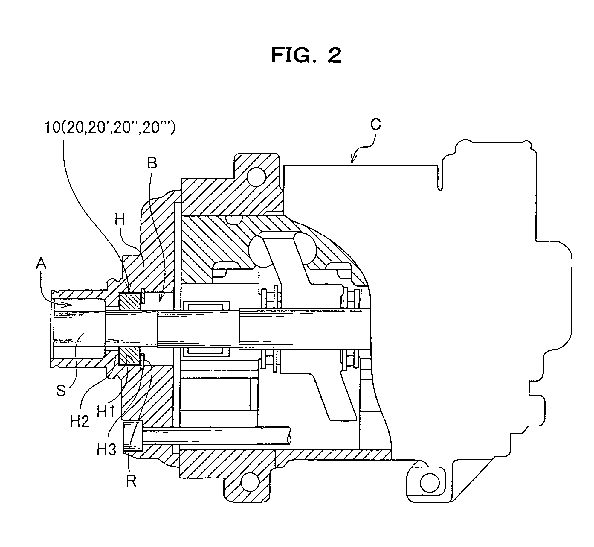
[0041]The most preferred embodiments of the present invention will be hereinafter described with reference to the attached drawings. Herein, a description is given of a case in which a lip-type seal according to the present invention is used in a compressor C that serves as a part of an air conditioning system, for example, of a vehicle.

[0042]As shown in FIG. 2, a compressor C includes a housing H that defines the outline, a rotational shaft S that is contained in the housing H and that transmits a rotational driving force to a compression mechanism from the outside, and a lip-type seal 10 that blocks the air A and an internal space B from each other by sealing a space between the outer peripheral surface of the rotational shaft S and the housing H therewith.

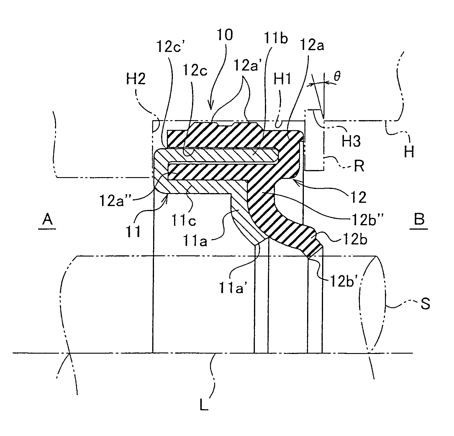
[0043]As shown in FIG. 3 and FIG. 4, the lip-type seal 10 is made up of a first reinforcing member 11 formed annularly and a first sealing member 12 formed annularly.

[0044]As shown in FIG. 3 and FIG. 4, the first reinforcing mem...


PUM


Abstract

The lip-type seal of the present invention is a lip-type seal with which the outer periphery of a rotational shaft (S) supported by a predetermined housing (H) is sealed. The lip-type seal is made up of a first annular reinforcing member (11) and a first sealing member (12). The first reinforcing member (11) includes a wall surface part (11a) defining a hole through which the rotational shaft (S) is passed and a cylindrical part (11b) bent from the outer edge of the wall surface part (11a). The first sealing member (12) includes an annular base (12a) that is joined to the housing (H), a first lip part (12b) that extends almost conical from the base (12a) inwardly in the radial direction and that comes into contact with the rotational shaft (S), and an annular concave part (11c) formed on the base (12a) so as to detachably fit the cylindrical part (11b). Accordingly, a desired sealing capability can be secured, and the components can be easily assembled, disassembled, and recycled.

Description

TECHNICAL FIELD[0001]The present invention relates generally to a lip-type seal with which the space between a housing and a rotational shaft, such as that of a compressor used in an air conditioning system of, for example, a vehicle, is sealed, and, more particularly to a lip-type seal that can be recycled.BACKGROUND ART[0002]In recent years, the technology for recycling a used lip-type seal has been developed as part of the environmental antipollution measures. As shown in FIG. 1, a conventional lip-type seal formed in consideration of recycling is known (see Japanese Published Unexamined Patent Publication No. 2002-364759, for example). This conventional lip-type seal is made up of a metallic core ring 1, a first rubber-made sealing member 2 that contains the core ring 1 and that is shaped almost conical, a second resinous sealing member 3 that adjoins the first sealing member 2 and that is shaped almost conical, and a metallic backup ring 4 that adjoins the second sealing member...

Claims


Application Information

Patent Timeline
Patent Type & Authority Patents(United States)
IPC IPC(8): F16J15/32F16J15/3232
CPCF16J15/3228F16J15/3268F16J15/3276F16J15/32
Inventor IKEDA, YASUHIRO
Owner EAGLE INDS
Why Eureka
Try Eureka