Connector

a technology of connectors and connector parts, applied in the direction of connection contact material, coupling device connection, instruments, etc., can solve the problem of limited space available for connector parts to overlap axially

Inactive Publication Date: 2008-03-18
SIEMENS AG
View PDF13 Cites 12 Cited by
  • Summary
  • Abstract
  • Description
  • Claims
  • Application Information

AI Technical Summary

Benefits of technology

[0020]The latching means may be releasable by an actuator or the like which may be operated externally of the connector or remotely. Thus release can be effected at the point when the connector parts are to be interengaged. Preferably, the latching means is releasable by engagement with the second connector part. Thus release can be effected automatically during the interengagement process. The arrangement is preferably such that the second connector part urges the latching means axially in order to effect release of the relatively movable portions.
[0021]The latching means may have a latch release portion and a latching portion which co-operate to effect release of the relatively movable portions of the first connector part. Thus, the latch release portion may act on the latching portion to cause it to release the relatively movable portions. The latch release portion may be urged axially rearwardly, preferably by the second connector part, to cause the latching portion to effect release. This may be achieved for example by at least one of the latch release portion and the latching portion having a surface slanted relative to the axial direction. In this type of arrangement, axial movement can be used to effect lateral movement and hence release of the latching portion. In a preferred embodiment, the latching portion has a slanted surface. The latch release portion may have a front facing surface for engagement by the second connector part and, rearwardly thereof, a part which co-operates with the latching portion. The latch release portion is preferably resiliently forwardly biased. When it is urged rearwardly against the resilient bias it can effect release of the latching portion.

Problems solved by technology

For example, in the case of making a connection horizontally into a tubing hanger with one connector part supported horizontally in the tubing hanger wall, the amount of space available for the connector parts to overlap axially is limited by the radial thickness of the tubing hanger wall.

Method used


Image

  • Connector
  • Connector
  • Connector

Examples


Embodiment Construction

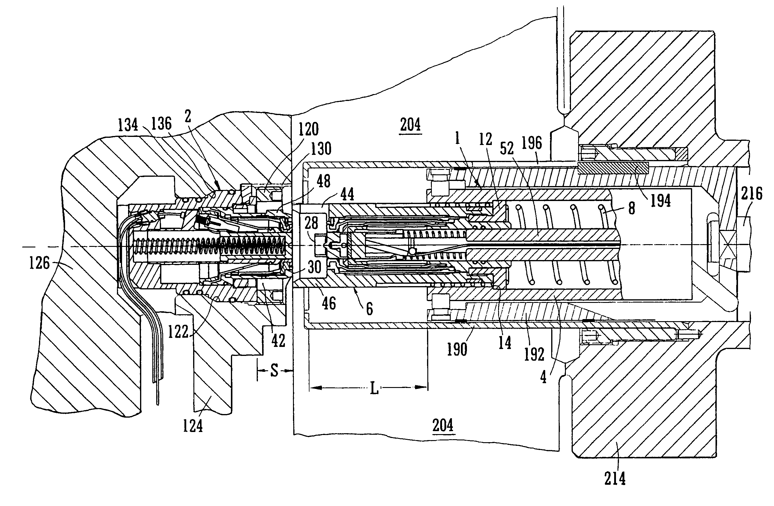
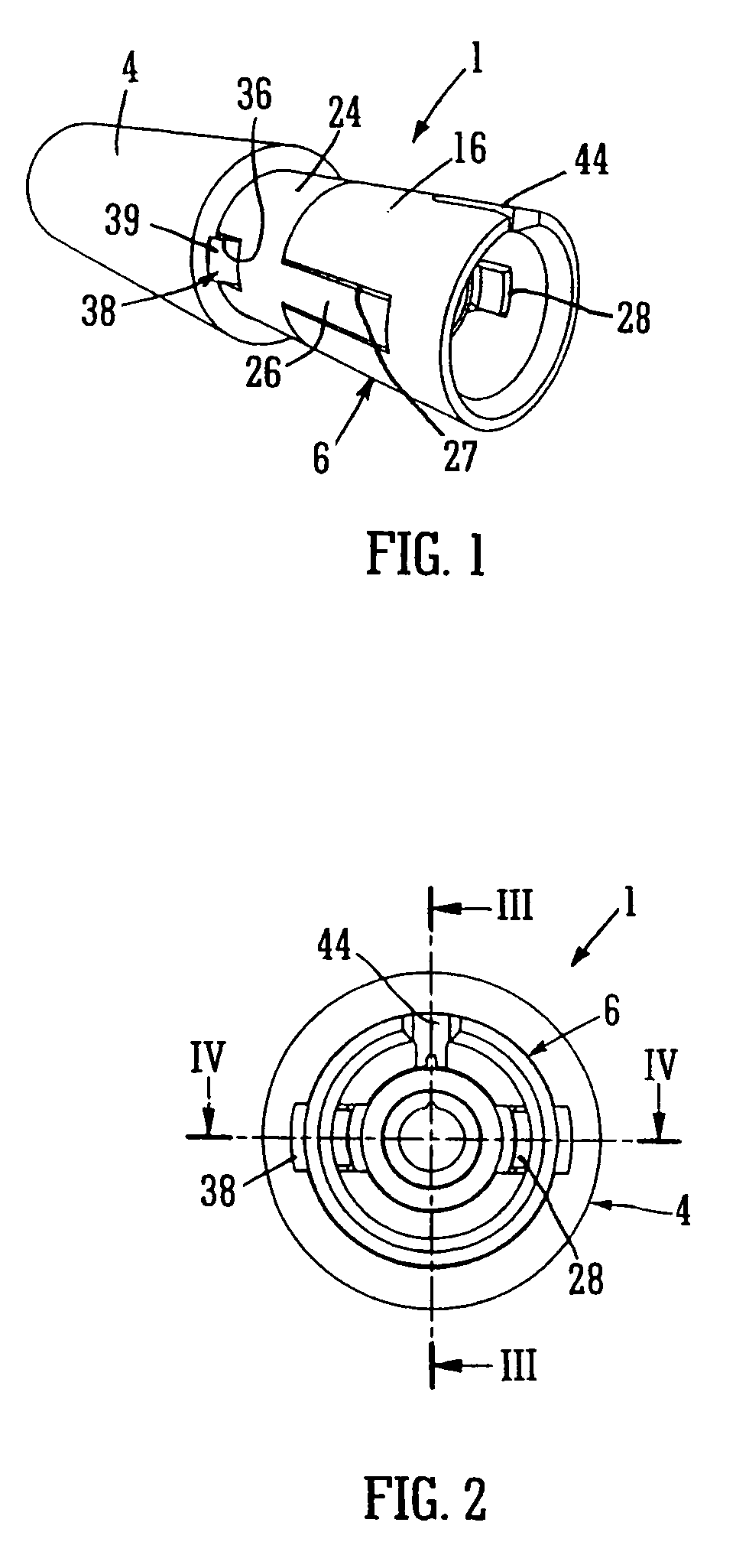
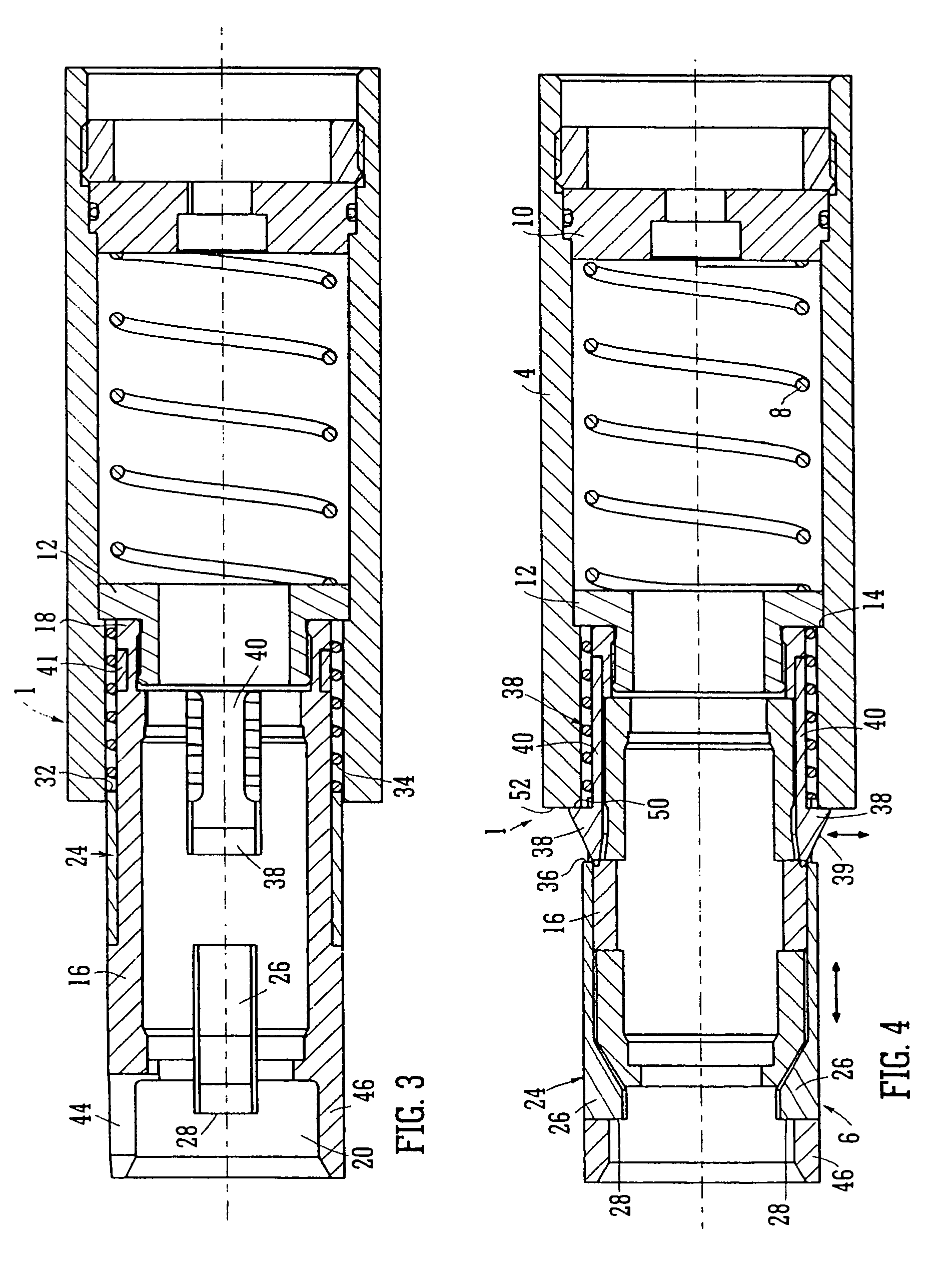
[0049]FIGS. 1 to 5 show a first connector part 1 and FIG. 8 shows a second connector part 2. The first connector part 1 has a housing 4 in which a shuttle 6 is axially movably located, biased to a forward position by a shuttle spring 8. The shuttle spring is seated against a rear wall 10 of the housing 4 and at its front it engages a collar 12 which abuts against a shoulder 14 of the housing.

[0050]The shuttle 6 has a cylindrical housing 16 which at its rear end 18 is fixed to the collar 12 and which has at its front end a forwardly projecting annular wall 46 forming a receptacle 20 for receiving a plug 22 of the second connector part 2 (see FIG. 8). The wall portion 46 has formed therein an axially extending alignment slot 44.

[0051]Latching means for latching the shuttle 6 to the housing 4 includes a latch release portion in the form of a latch release sleeve 24 and a latching portion in the form of a pair of latch arms 40. The latch release sleeve 24 is fitted around the cylindrica...


PUM


Abstract

A connector for making an optical and/or electrical connection underwater or in a wet or severe environment, comprising first and second connector parts which are axially interengageable to establish the optical or electrical connection, the first connector part having relatively movable portions for relative movement to allow the optical or electrical connection to be established when the first and second connector parts are interengaged, and having latching means to prevent such relative movement. The latching means is preferably releasable by engagement with the second connector part.

Description

CROSS-REFERENCE TO RELATED APPLICATION[0001]This application claims the priority of U.S. Provisional Patent Application No. 60 / 627,730 filed Nov. 12, 2004.BACKGROUND OF THE INVENTION[0002]This invention relates to a connector for making an optical and / or electrical connection underwater or in a wet or severe environment.[0003]Optical fibres are frequently used for communication purposes, and it is often necessary to form an optical connection between the ends of such fibres. This generally involves bringing together two connector components each supporting a respective fibre and making end-to-end contact between the fibres. In the case of underwater connectors, it is known to provide the connector components with end sealing arrangements so that the optical fibre ends are protected from the outside environment when the components are in a disconnected state, the end sealing arrangements opening up during connection to allow passage of one of the optical fibre ends therethrough in or...

Claims


Application Information

Patent Timeline
Patent Type & Authority Patents(United States)
IPC IPC(8): G02B6/38
CPCG02B6/3816H01R13/523
Inventor MCKINNON, GILLIAN ANNE
Owner SIEMENS AG
Why Eureka
Try Eureka