Microprocessor controlled booster apparatus with polarity protection

a microprocessor control and booster technology, applied in the direction of reverse polarity correction, safety/protection circuits, transportation and packaging, etc., can solve the problem of one or both batteries being short-circuited, the connection can be very dangerous, and the voltage difference between a battery with sufficient electric power and a battery with insufficient electric power can be too large to achieve the effect of preventing current flow

Inactive Publication Date: 2008-03-18
VECTOR PRODS
View PDF78 Cites 34 Cited by
  • Summary
  • Abstract
  • Description
  • Claims
  • Application Information

AI Technical Summary

Benefits of technology

[0011]Typically, a battery booster device comprises a pair of cables connected at one end to a built-in battery or other power source arranged in a portable box. The other ends of the cables are connected to a pair of alligator clamps. The built-in battery provides a DC power source for boosting a depleted battery. When the clamps ar

Problems solved by technology

Making this connection, however, can be very dangerous if the batteries are connected incorrectly.
A battery has a small internal resistance, and there is a voltage difference between a battery with sufficient electric power and a battery with insufficient electric power.
Additionally, incorrect connection may result in one or both of the batteries being short-circuited.
Under such conditions, one or both of the batteries may be damaged, and in some cases, an explosion, fire and damage to the vehicle or to a person may result.
The failure of an engine of an automobile to start due to insufficient electric power, in a

Method used


Image

  • Microprocessor controlled booster apparatus with polarity protection
  • Microprocessor controlled booster apparatus with polarity protection
  • Microprocessor controlled booster apparatus with polarity protection

Examples


Embodiment Construction

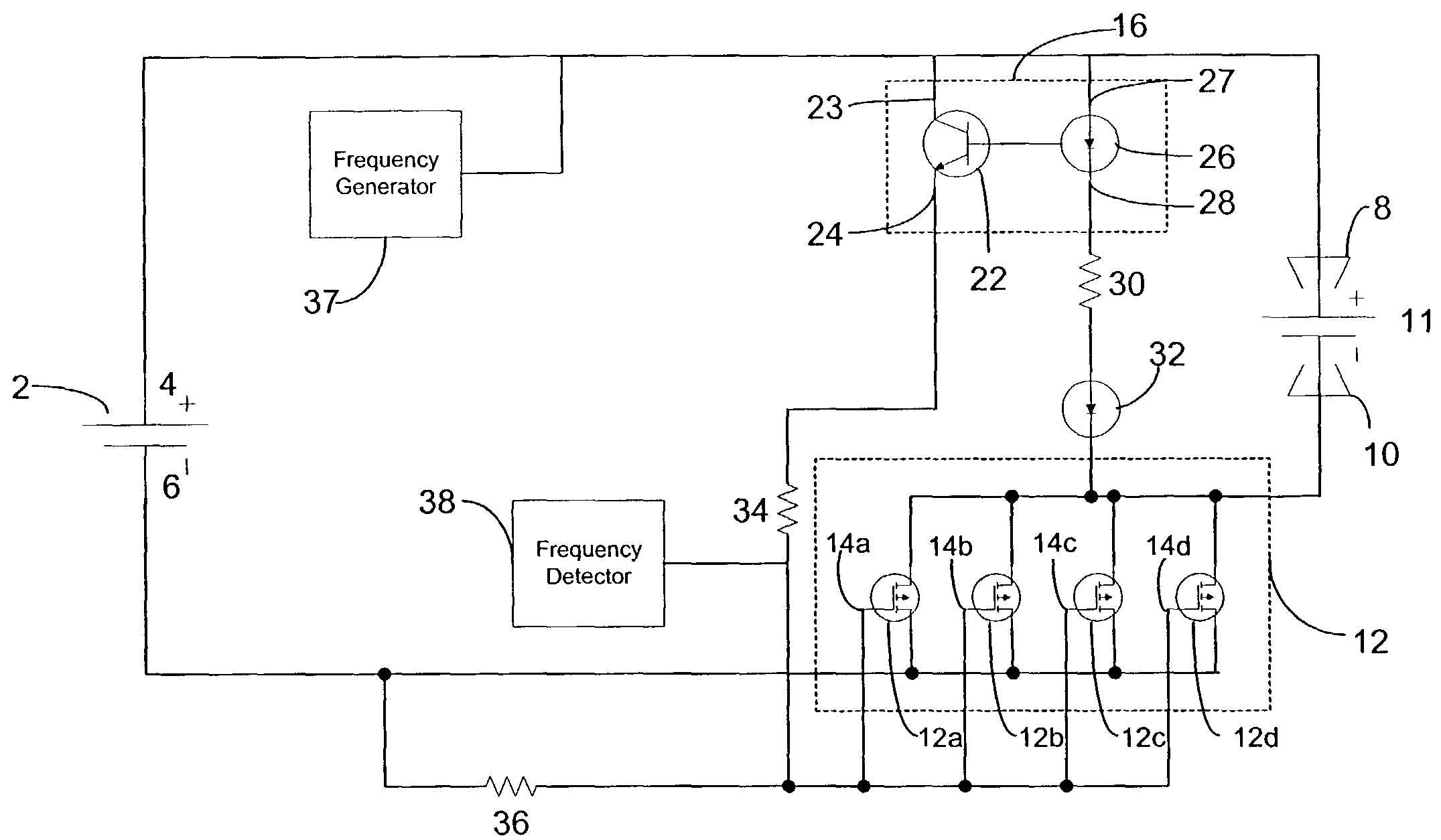
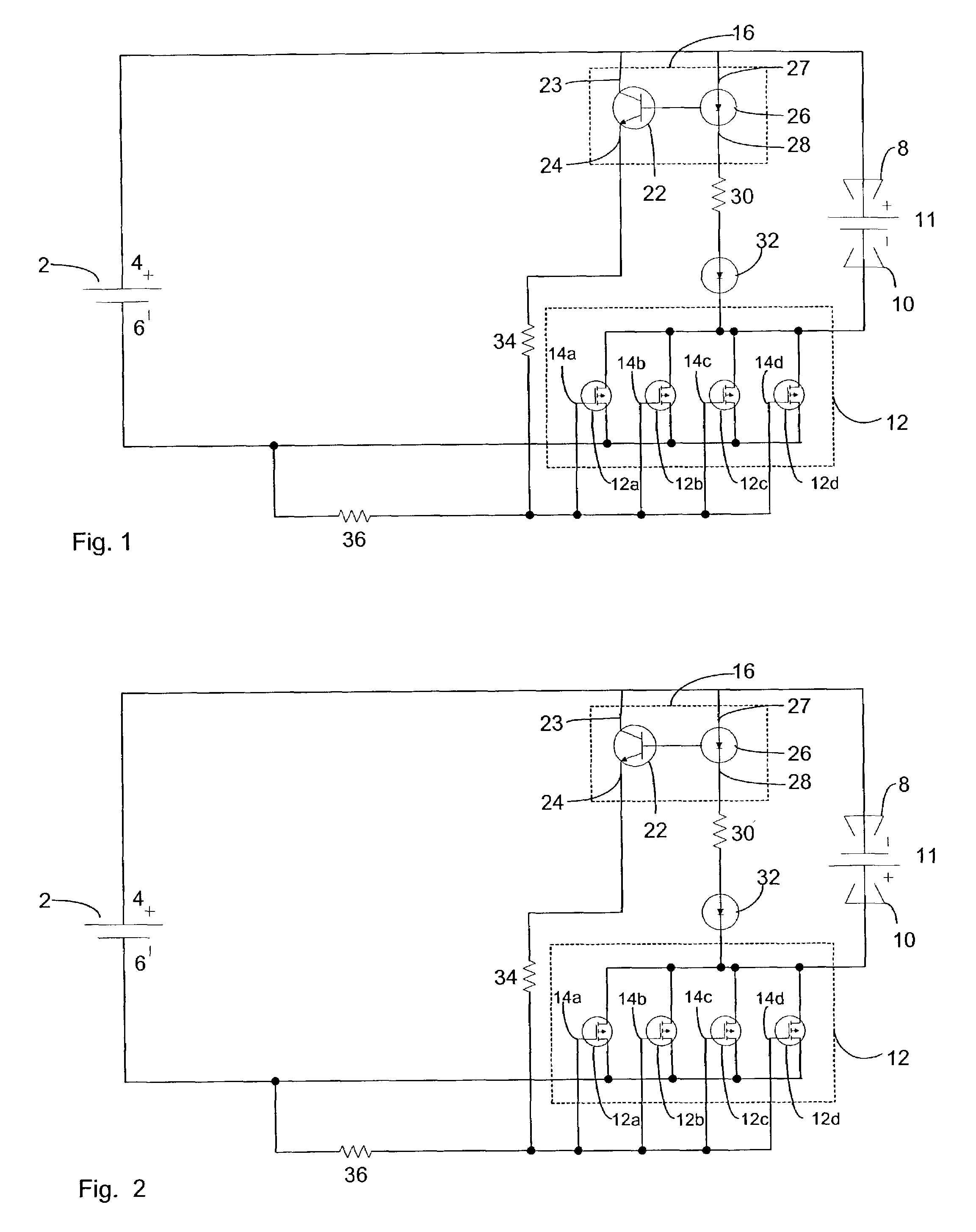
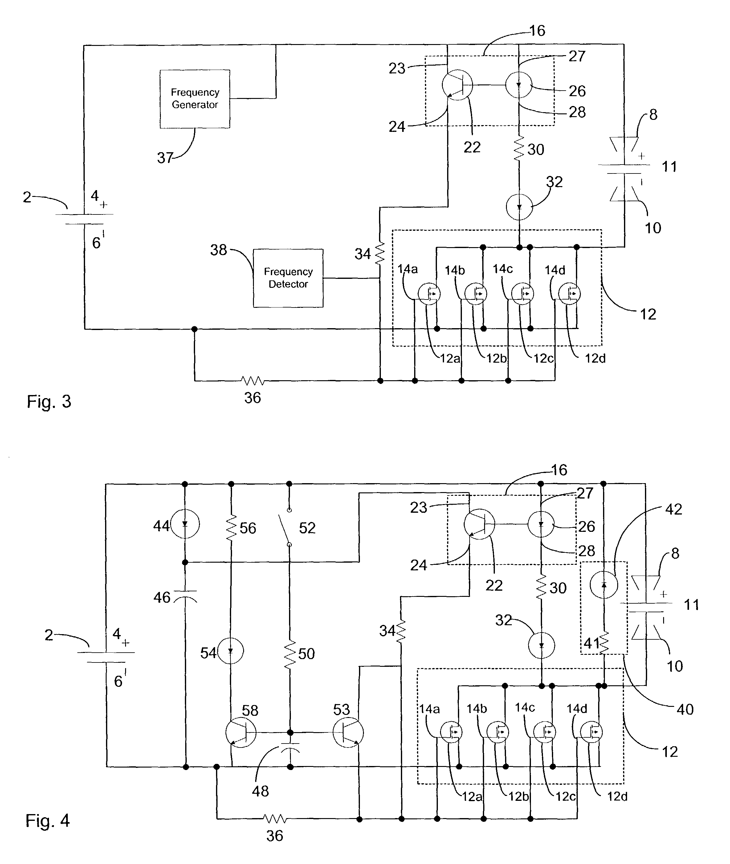
[0028]FIG. 1 illustrates a battery booster device including a polarity protection circuit according to an exemplary embodiment of the invention. A boosting battery 2 with a positive terminal 4 and a negative terminal 6 is provided in the booster device. The positive terminal 4 of the boosting battery 2 is coupled to one of a pair of alligator clamps 8, 10 to be connected to a battery to be charged 11 (depleted battery) via a wire or battery cable. The negative terminal 6 of the boosting battery 2 is connected to the other of the alligator clamps 8, 10 to be connected to the battery to be charged 11 via a wire or battery cable.

[0029]A switch 12 is coupled to one of the wires or battery cables to be connected to the depleted battery 11. The switch 12 is activated to complete a boosting circuit between the boosting battery 2 and the depleted battery 11 only when a correct polarity connection between the batteries is attained. In the embodiment shown, the switch 12 is arranged between t...


PUM


Abstract

A polarity protection circuit for a battery booster device is provided. According to an exemplary embodiment, the polarity protection circuit is comprised of solid-state devices. Preferably no mechanical or electro-mechanical devices, such as solenoids are included in the polarity protection circuit. The polarity protection circuit is electrically connected to the battery to be charged and to the boosting battery. The polarity protection circuit prevents current flow between the batteries unless proper polarity is achieved.

Description

CROSS-REFERENCE TO RELATED APPLICATIONS[0001]This application claims priority from U.S. Provisional Application Ser. Nos. 60 / 357,146 filed Feb. 19, 2002 and 60 / 369,839 filed Apr. 5, 2002, the contents of both of which are incorporated herein by reference.FIELD OF THE INVENTION[0002]The present invention relates to a booster device used for boosting a depleted battery and in particular to microprocessor control of the booster apparatus and a polarity protection circuit.BACKGROUND OF THE INVENTION[0003]It is well known that when an engine of an automobile is not able to be started due to insufficient electric power, a battery of the automobile can be jump started by power from a battery of another automobile or from a battery in a booster device to thereby start the engine.[0004]To boost the battery of the automobile which is of insufficient electric power by power from another battery, the two batteries must be connected through a pair of electric wires. For example, the positive ter...

Claims


Application Information

Patent Timeline
IPC IPC(8): H02J7/00
CPCH02J7/0034
Inventor KRIEGER, MICHAELRANDOLPH, BRUCE
Owner VECTOR PRODS
Why Eureka
Try Eureka