Optical image measuring apparatus and optical image measuring method for forming a velocity distribution image expressing a moving velocity distribution of the moving matter

a technology of optical image and velocity distribution, which is applied in the field of optical image measuring apparatus and optical image measuring method for forming a velocity distribution image expressing a moving velocity distribution of the moving matter, can solve the problems of not being able to accurately use the apparatus in fields that require high resolution images, and the current available ccd camera cannot follow the beat frequency of a heterodyne,

Inactive Publication Date: 2008-03-18
KK TOPCON
View PDF9 Cites 41 Cited by
  • Summary
  • Abstract
  • Description
  • Claims
  • Application Information

AI Technical Summary

Benefits of technology

[0025]Another object of the present invention is to provide an optical image measuring apparatus capable of effectively measuring an object to be measured over a wide range in order to measure an image expressing a distribution such as a flow velocity distribution of blood flowing through a blood vessel of a living tissue, and an optical image measuring method for the optical image measuring apparatus.
[0045]According to the present invention, the measurement is performed using the light beam whose beam diameter is increased, so it is unnecessary to perform scanning while the object to be measured is moved in directions (x-y directions) orthogonal to the propagating direction of the signal light. Even when the object to be measured is the living tissue, it is possible to effectively measure the object to be measured over a wide range in order to measure the velocity distribution image expressing a distribution such as a flow velocity distribution of blood flowing through the blood vessel of the living tissue.

Problems solved by technology

In addition, it is hard to shorten a measurement time in view of measurement fundamentals.
Therefore, it is supposedly hard to actually use the apparatus in fields that require a high resolution image, such as a medical field and an industrial field.
However, up to now, a problem has been recognized that a currently available CCD camera cannot follow the beat frequency of a heterodyne signal which is the order of several kHz to several MHz because of the low frequency response characteristic thereof.
However, according to the technique described in JP 2002-214130 A, when the object to be measured is to be measured over a wide range, a mechanism for moving the object to be measured to scan measurement positions (sample stage) is necessary, which leads to a problem in that the measurement takes a long time.
When the technique described in JP 2002-214130 A is to be applied to living tissue measurement, in particular, when the flow velocity of blood flowing through the retina blood vessel of a human eye is to be measured, it may be difficult to scan the measurement positions by moving the living tissue itself in view of an apparatus structure, measurement accuracy, and the like.

Method used


Image

  • Optical image measuring apparatus and optical image measuring method for forming a velocity distribution image expressing a moving velocity distribution of the moving matter
  • Optical image measuring apparatus and optical image measuring method for forming a velocity distribution image expressing a moving velocity distribution of the moving matter
  • Optical image measuring apparatus and optical image measuring method for forming a velocity distribution image expressing a moving velocity distribution of the moving matter

Examples


embodiment

Firsr Embodiment

[0066]A first embodiment of the present invention will be described. In this embodiment, a plurality of polarized light components included in interference light having information related to the object to be measured are detected to form an image of the object to be measured.

[Structure of Apparatus]

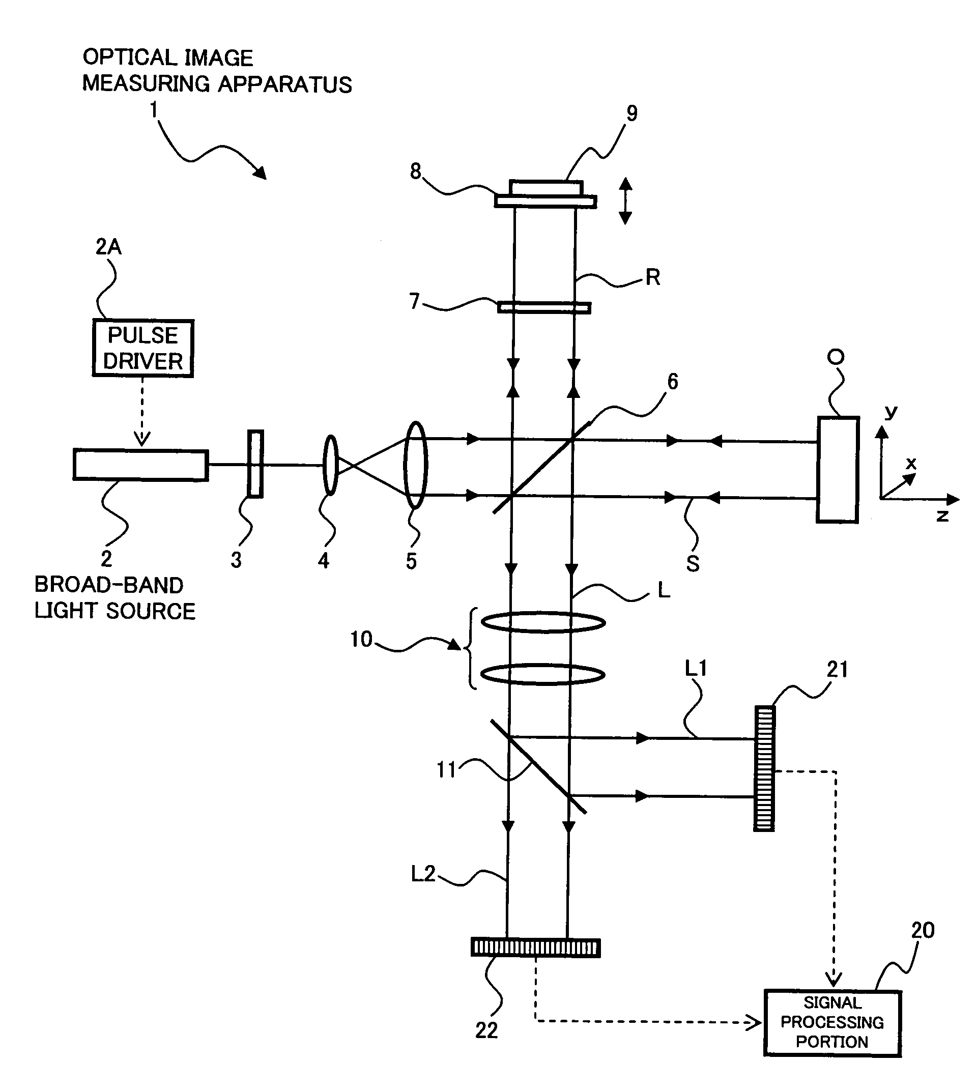
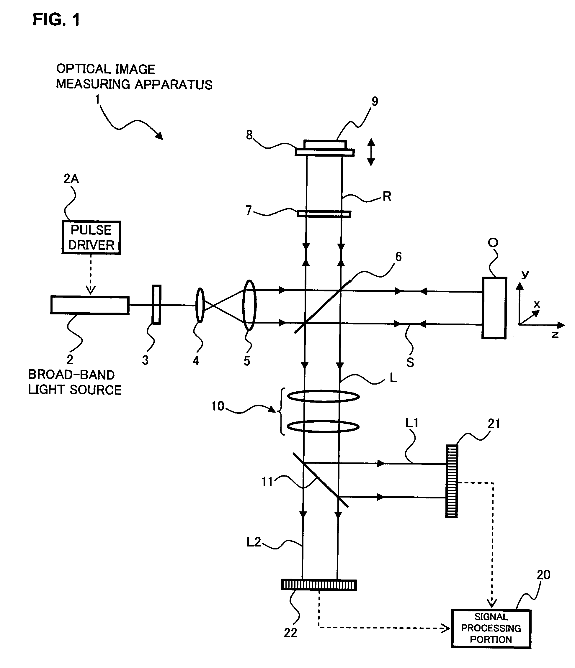
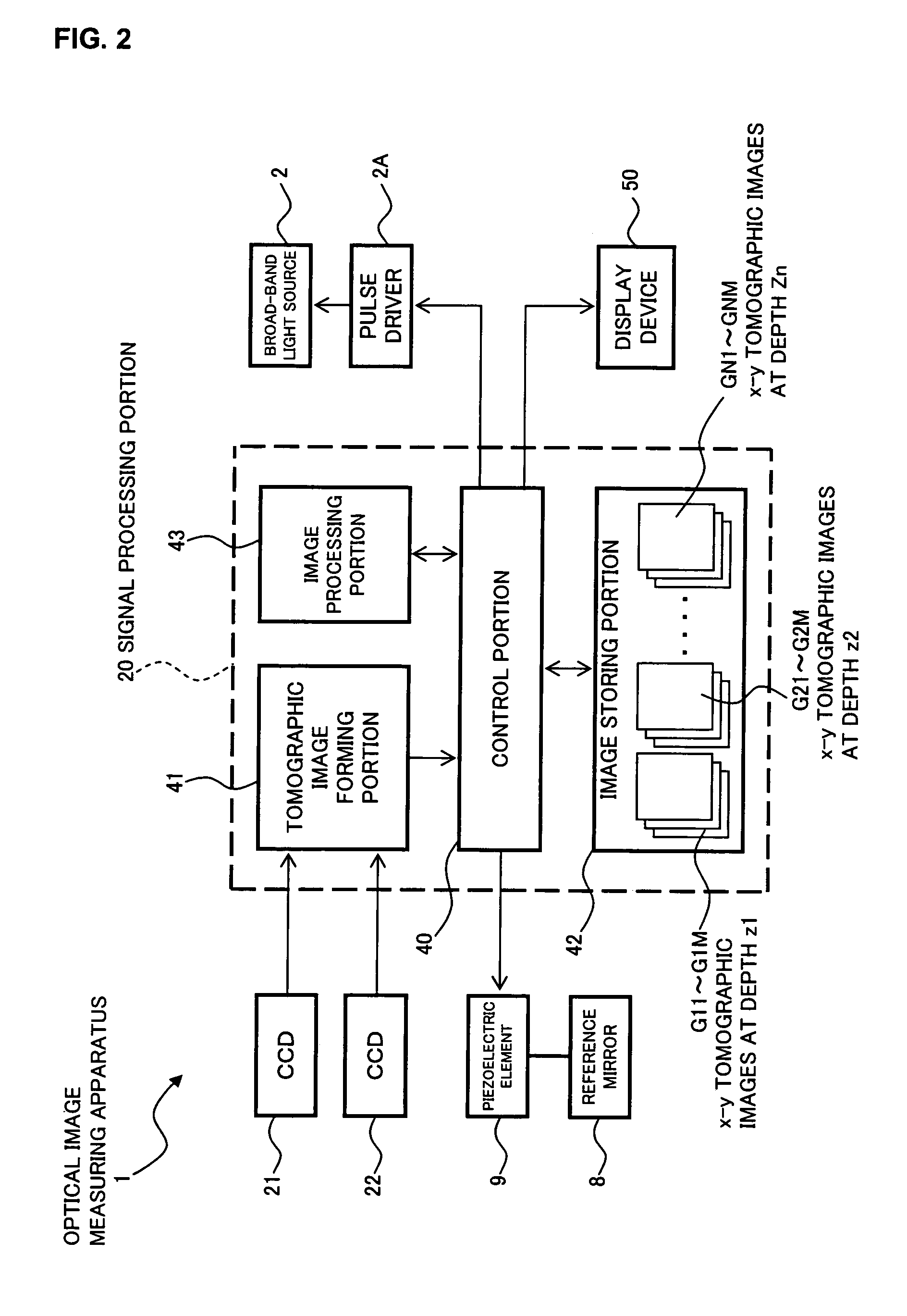
[0067]An optical image measuring apparatus according to the first embodiment of the present invention will be described with reference to FIGS. 1 and 2. FIG. 1 illustrates a schematic structure of an optical system of the optical image measuring apparatus according to this embodiment and FIG. 2 illustrates a structure of a control system thereof.

[Structure of Optical System]

[0068]First, the optical system of the optical image measuring apparatus according to this embodiment will be described with reference to FIG. 1. The optical image measuring apparatus 1 shown in FIG. 1 includes a broad-band light source 2 for outputting a low-coherent light beam, a polarizing plate 3 f...

first embodiment

MODIFIED EXAMPLES IN FIRST EMBODIMENT

[0169]Hereinafter, modified examples in this embodiment will be described.

modified example 1

[0170]FIG. 7 illustrates a modified example of the optical image measuring apparatus 1. An optical image measuring apparatus 1′ shown in FIG. 7 includes the same structure as that of the optical image measuring apparatus 1 except for a frequency shifter 12 disposed on the optical path of the reference light R. The frequency shifter 12 composes “frequency shifting means” in the present invention and shifts a frequency of the reference light R before and after it is reflected on the reference mirror 8. The frequency shifter 12 is composed of, for example, an optoelectronic modulator or an acoustooptic modulator.

[0171]The frequency shifter 12 is used to satisfy the above-mentioned condition (fD′>fD: the amount of frequency shift applied to the signal light S) related to the amount of frequency shift fD′ applied to the reference light R, or in the case where it is difficult or impossible to detect the interference light, such as the case where the amount of frequency shift applied to th...


PUM


Abstract

An optical image measuring apparatus capable of speedily measuring a velocity distribution image of a moving matter. Including a broad-band light source, lenses for increasing a beam diameter, a polarizing plate converting the light beam to linearly porlarized light, and a half mirror, a wavelength plate converting the reference light to circularly polarized light, the half mirror superimposing the signal light whose frequency is partially shifted by the moving matter in the object and the reference light is circularly polarized light to produce superimposed light including interference light, CCDs for receiving different polarized light components of the interference light, and outputting detection signals including interference frequency components corresponding to beat frequencies of the interference light, and a signal processing portion for forming velocity distribution image based on interference frequency component corresponding to a beat frequency equal to an intensity modulation frequency of the light beam.

Description

BACKGROUND OF THE INVENTION[0001]1. Field of the Invention[0002]The present invention relates to an optical image measuring apparatus employing a structure in which an object to be measured which is particularly a light scattering medium is irradiated with a light beam and a surface form or inner form of the object to be measured is measured based on a reflected light beam or a transmitted light beam to produce an image of a measured form, and to an optical image measuring method for the optical image measuring apparatus. In particular, the present invention relates to a technique for producing an image expressing a moving velocity of a moving matter such as a fluid flowing through the object to be measured, which is used for an optical image measuring apparatus for producing an image of the object to be measured by using an optical heterodyne detection method and an optical image measuring method for the optical image measuring apparatus.[0003]2. Description of the Related Art[0004...

Claims


Application Information

Patent Timeline
Patent Type & Authority Patents(United States)
IPC IPC(8): G01B11/24
CPCA61B3/102A61B5/0059A61B5/0066G01P5/001G01P5/26G01B9/02045G01B9/02002G01B9/02091G01B9/02014G01B9/02081G01B2290/70G01B2290/45
Inventor CHAN, KINPUIAKIBA, MASAHIROFUKUMA, YASUFUMI
Owner KK TOPCON
Why Eureka
Try Eureka