Feedback controller for PWM amplifier

a technology of a feedback controller and an amplifier, which is applied in the direction of amplifiers, dc amplifiers with modulator-demodulator, semiconductor devices/discharge tubes, etc., can solve the problems of reducing the accuracy requirement of system power supply, and affecting the performance of amplifiers. , to achieve the effect of avoiding unnecessary high-frequency activity, avoiding spurious low-frequency output signal components, and being more robust against variations

a technology of a feedback controller and an amplifier, which is applied in the direction of amplifiers, dc amplifiers with modulator-demodulator, semiconductor devices/discharge tubes, etc., can solve the problems of reducing the accuracy requirement of system power supply, and affecting the performance of amplifiers. , to achieve the effect of avoiding unnecessary high-frequency activity, avoiding spurious low-frequency output signal components, and being more robust against variations

US7348840B2Active Publication Date: 2008-03-25CIRRUS LOGIC INC

Image

  • Feedback controller for PWM amplifier
  • Feedback controller for PWM amplifier
  • Feedback controller for PWM amplifier

Examples


Embodiment Construction

Background

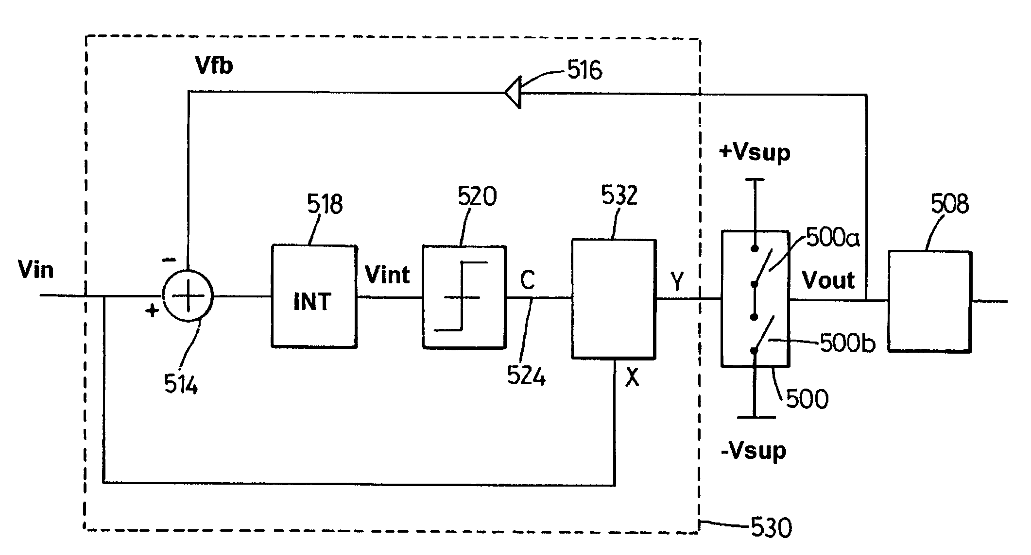
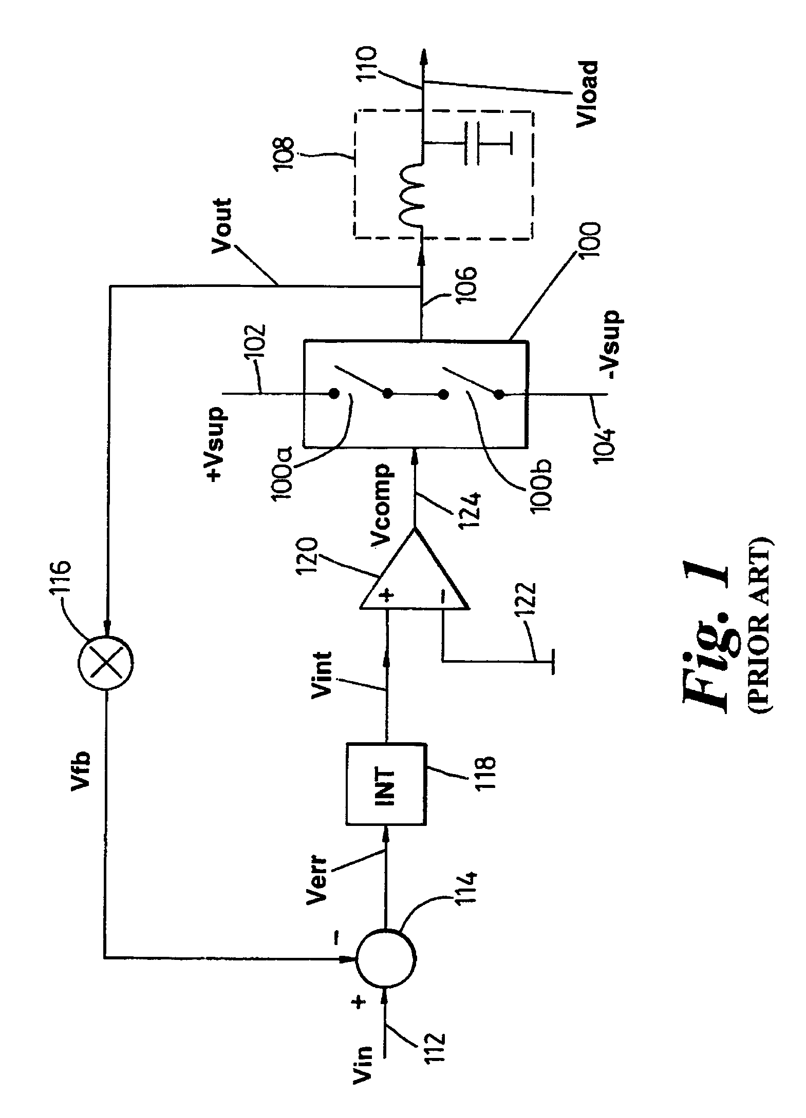
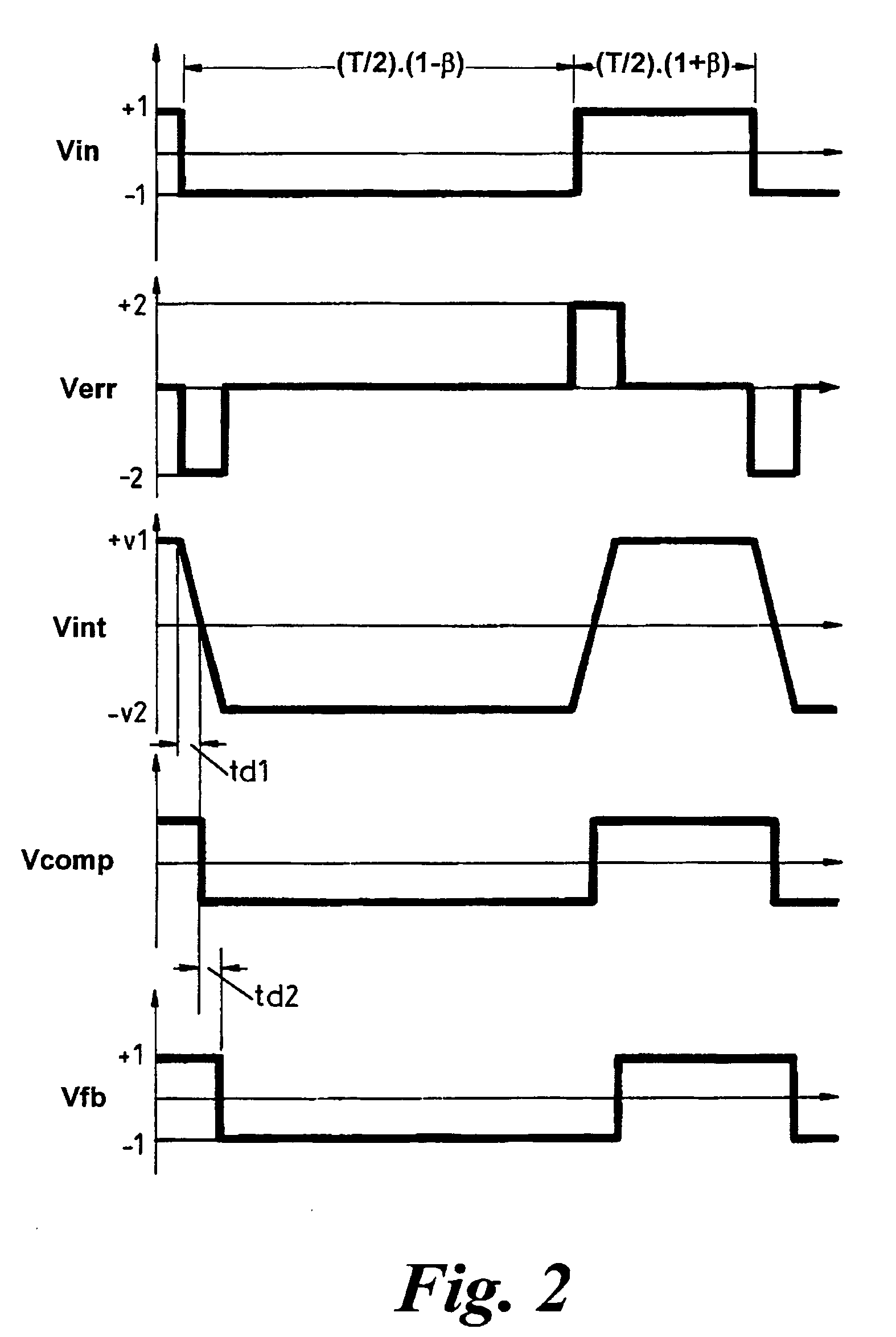
[0071]FIG. 1 shows the overall architecture of a known PWM amplifier circuit with feedback control. The input is a PWM waveform Vin corresponding to a desired analogue audio signal. If the preceding PWM modulator is digital, Vin's edges will probably be quantised in time, aligned to some very high speed clock; if the preceding modulator is analogue, the edges will generally not be constrained to discrete time points.

[0072]The PWM amplifier comprises a power switch 100 comprising a pair of controllable switches 100a and 100b such as power MOSFETs coupled in a push-pull arrangement between positive and negative supply rails 102 (+Vsup) and 104 (−Vsup). The output 106 of the power switch is coupled through a low-pass output filter 108 to output terminal 110 which imposes a voltage waveform Vload on whatever load is to be driven. Input terminal 112 is connected to a positive input of a subtractor 114. Signal Vout from the output 106 or power switch 100 is also fed via an atten...


PUM


Abstract

A feedback controller in a PWM amplifier comprises a signal input for receiving a pulse width modulated (PWM) input signal (Vin) whose duty cycle represents a desired analogue output signal. A feedback loop filter 518 generates a filtered error signal (Vint) comprising a filtered representation of differences between the input signal (Vin) and a feedback signal (Vfb). A comparator (520) compares the filtered error signal with a reference to generate a provisional PWM switching control signal (C) for controlling the PWM amplifier (500). A pulse conditioner (532) receives both the provisional PWM switching control signal (C) and the PWM input signal (X=Vin) and outputs to the amplifier (500) a conditioned PWM switching control signal (Y), modified in accordance with predetermined constraints in relation to the PWM input signal. The pulse conditioner includes a single pulse function (534) whereby only a single pulse is permitted for every pulse in the input signal, thereby eliminating oscillations that can otherwise Occur under over-voltage supply conditions. Missing pulse and minimum pulse width functions (536, 538) can also be provided.

Description

PRIOR APPLICATION DATA[0001]The present application claims priority from United Kingdom application 0516823.2, filed on Aug. 17, 2005, the disclosure of which is incorporated herein by reference in its entirety.FIELD OF THE INVENTION[0002]The invention relates to a feedback controller for use in a pulse width modulated (PWM) amplifier, and to an amplifier circuit including such a controller. The invention further relates to a method of controlling a PWM amplifier.BACKGROUND[0003]PWM techniques have recently started to become prevalent in hi-fi audio, to give “Class D” or “switching” output stages. PWM power amplifiers also find application in a range of applications including motor control.[0004]The high efficiency offered by these techniques minimises driver power dissipated in the driver transistors, so small and simple cheap packages can be used even for 100 W power amplifiers, rather than expensive special low-thermal-resistance packages. Savings in system cost and a smaller phy...

Claims


Application Information

Patent Timeline
25 Mar 2008
Publication
US7348840B2
IPC
H03F3/38; H03F1/32; H03F1/34; H03F3/217; H03F3/30
CPC
H03F1/32; H03F1/3217; H03F1/34; H03F3/217; H03F3/2173; H03F3/30; H03F2200/351; H03F2200/78
Inventors
MAGRATH, ANTHONY JAMES; WESTLAKE, JOHN