
RFID cabinet

a technology of rfid cabinet and rfid plate, which is applied in the field of rfid plate, can solve the problems of inflexibility, high cost, and special packaging, and achieve the effects of reducing the number of rfid pla

Active Publication Date: 2008-03-25
OMNICELL
View PDF33 Cites 268 Cited by
  • Summary
  • Abstract
  • Description
  • Claims
  • Application Information

AI Technical Summary

Benefits of technology

This solution ensures accurate and automated tracking and monitoring of medical inventory, reducing errors and the need for manual counting, while allowing for flexible access control and efficient restocking, enhancing product security and usability in medical environments.

Problems solved by technology

In developing such systems, the challenge lies in balancing convenience and speed of access along with entering the necessary data to identify the user, the product and the account number or patient.
Systems that dispense an individual product in the same manner as a candy machine, while desirable for convenience and security, are usually too expensive, require special packaging, and are not flexible in terms of the various size and configurations of product that need to be stocked in a hospital.
They are also not very space efficient, since items are individually spaced and housed.
This is particularly true of expensive product where it is worth incurring the additional expense of applying the RFID tags.
RFID tags are not currently available on products like bar codes, and are not likely to be generally available on healthcare products for many years.

Method used


Image

  • RFID cabinet
  • RFID cabinet
  • RFID cabinet

Examples


Embodiment Construction

[0012]Described below are several exemplary embodiments of the invention. Although certain features are described, for ease of discussion, in relation to certain illustrated embodiments, those skilled in the art will appreciate, based on the disclosure herein, that various of the inventive features can be combined in accordance with many different embodiments of the invention. The illustrated embodiments below, therefore, are provided merely by way of example and should not be considered to limit the scope of the invention, which is defined only by the appended claims.

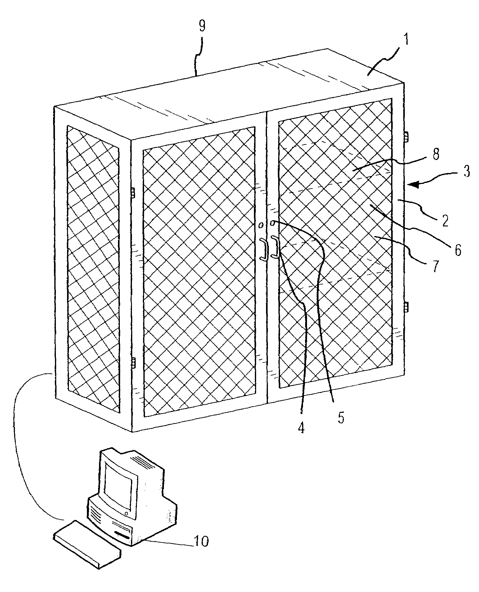
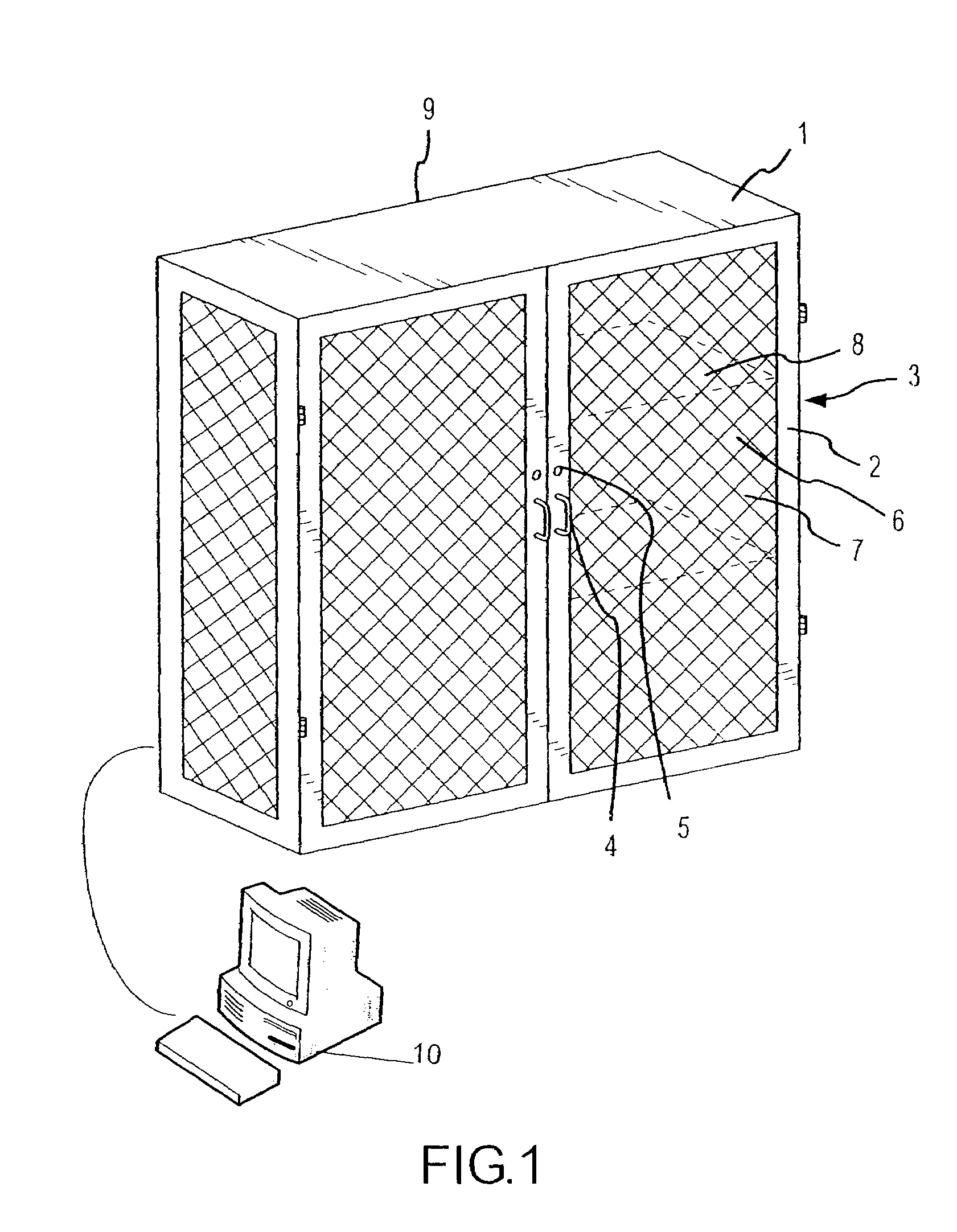
[0013]One aspect of the invention provides a cabinet with a locking door, or multiple individually controlled doors. In another aspect, the invention may provide a room (or multiple rooms) with an electronically controlled lock. The cabinet or room may contain multiple quantities of multiple items.

[0014]Certain items require specific shelving fixtures because certain items contain a liquid or metal content that prevent...


PUM


Abstract

An RFID for cabinet for monitoring items having an RFID tag includes a cabinet having at least one locking front door. An RFID detector is used for monitoring each item placed within the cabinet and is located within the interior of the cabinet. A computer is coupled to the RFID cabinet and controls opening and closing of the front door and is configured to receive an input that identifies the user. In this way, the computer is configured to periodically record data read from the RFID tags by the RFID detector.

Description

CROSS REFERENCE TO RELATED APPLICATIONS[0001]This application is a non-provisional application and claims the benefit of U.S. provisional application No. 60 / 592,907, filed Jul. 29, 2004, the complete disclosure of which is herein incorporated by reference.BACKGROUND OF THE INVENTION[0002]In the healthcare industry, the availability of supply products is critical. Various systems exist that provide tracking of product usage, quick replenishment, user tracking, and patient tracking for billing purposes.[0003]In addition, closed cabinet systems exist that prevent the removal of items without the entry of necessary data to perform the above tracking and prevent diversion or theft. Such a system is particularly applicable to the expensive items that are used in an operating room (OR) or cath lab. However, closed cabinet systems are also applicable to the high volume diversion of inexpensive items that are useful outside the healthcare facility such as batteries, bandages, shampoos, pens ...

Claims


Application Information

Patent Timeline
Patent Type & Authority Patents(United States)
IPC IPC(8): G08B13/14
CPCG08B13/2417G06K17/00F25D2700/08G07G1/009G07G1/0045G07F9/026G06Q20/203G08B13/14G08B13/00
Inventor HIGHAM, JOHN
Owner OMNICELL
Learn More