
Light source apparatus and projection apparatus

a technology of projection apparatus and light source, which is applied in the direction of lighting and heating apparatus, static indicating devices, instruments, etc., can solve the problems of large noise in cooling, large electrical power consumption of projection apparatus, and many problems of cost and usability of projection apparatus

Active Publication Date: 2008-03-25
CASIO COMPUTER CO LTD
View PDF2 Cites 80 Cited by
  • Summary
  • Abstract
  • Description
  • Claims
  • Application Information

AI Technical Summary

Benefits of technology

The present invention relates to a light source apparatus and a projection apparatus. The light source apparatus includes a pyramidal or prismoidal light source housing with multiple inclined surfaces, each containing a dichroic mirror that transmits and reflects light of different wavelengths. The light source housing has an opening for emitting light, which can be directed towards an object or reflected once by the dichroic mirrors before being directed. The projection apparatus includes a light modulating section that forms a projection optical image by combining the light emitted from the light source housing. The technical effects of the invention include improved color accuracy, reduced light loss, and improved image quality.

Problems solved by technology

However, such projector apparatuses have many problems in cost and usability.
For example, they consume a large amount of electric power, radiate much heat and causes noises in great deal for cooling.
Further, they easily deteriorate despite their expensive prices if their temperatures are not appropriately controlled by proper cooling, and their lives become short.
However, illumination obtained by one LED is still much lower than that of the above ultra-high voltage mercury lamps and the like.
Therefore, the size of the available panel is equal to the opening size of the rod lens 20, and thus the number of LEDs which can be arranged is also limited.

Method used


Image

  • Light source apparatus and projection apparatus
  • Light source apparatus and projection apparatus
  • Light source apparatus and projection apparatus

Examples


Embodiment Construction

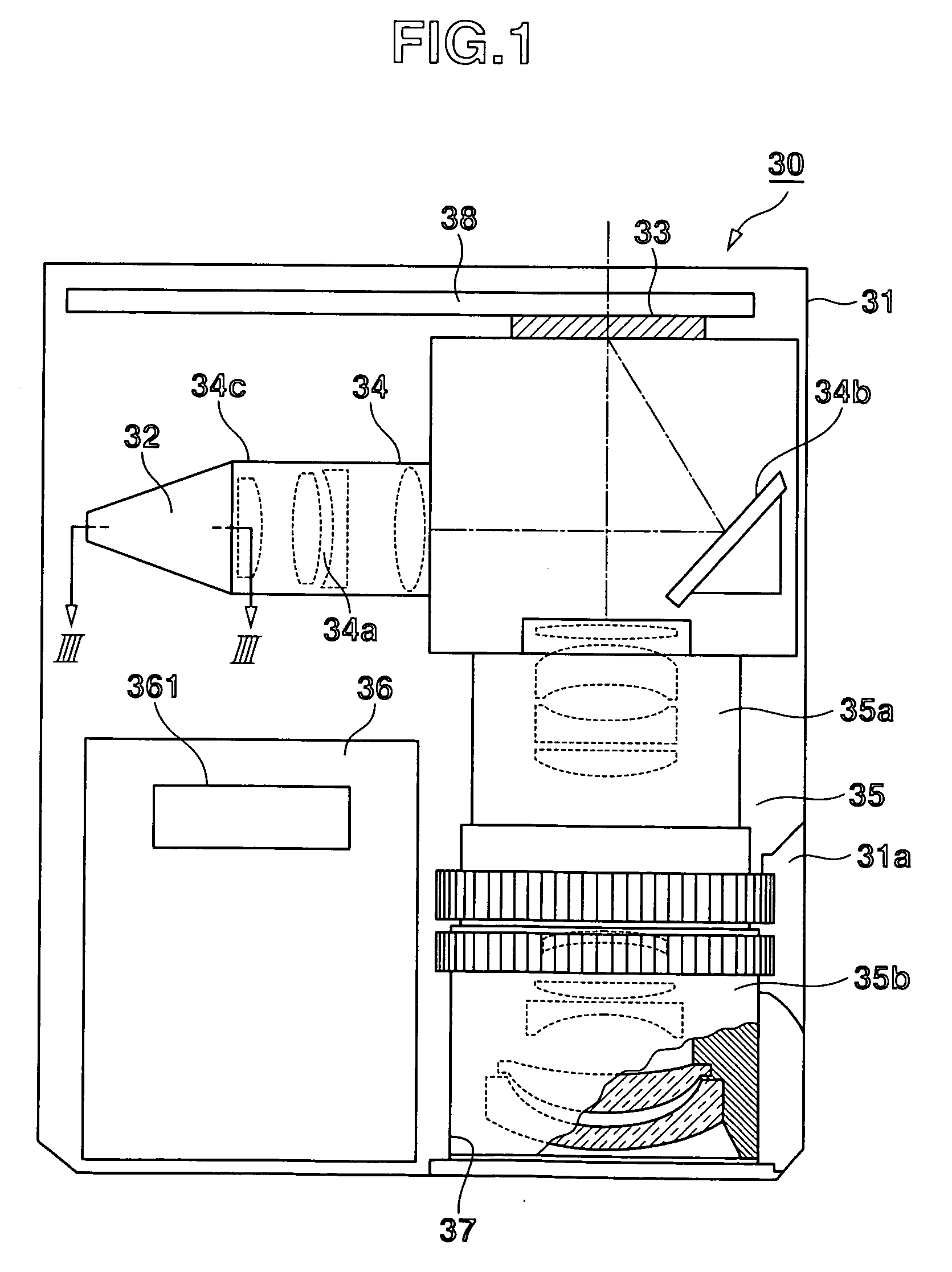
[0035]An embodiment of the present invention if the present invention is applied to a projector apparatus 30 is explained with reference to drawings.

[0036]FIG. 1 is a cross-sectional plan view of the projector apparatus 30. The projector apparatus 30 has a structure wherein a light source apparatus 32 (light source section), a display element 33 (light modulating section), a light-source side optical system 34, and a projection lens 35 (projection section) are arranged in an inverted L shape in a projector case 31 having a rectangular shape in plan, and a power source section 36 is disposed in a remaining space in the projector case 31. The display element 33 has a display area in which a plurality of pixels are arranged in a matrix in row and column directions, and displays an image by controlling outgoing of light incident on the pixels. The light-source side optical system 34 makes the outgoing light from the light source apparatus 32 incident on the display element 33. The proje...


PUM

PropertyMeasurementUnit
wavelengthaaaaaaaaaa
widthsaaaaaaaaaa
wavelengthaaaaaaaaaa

Abstract

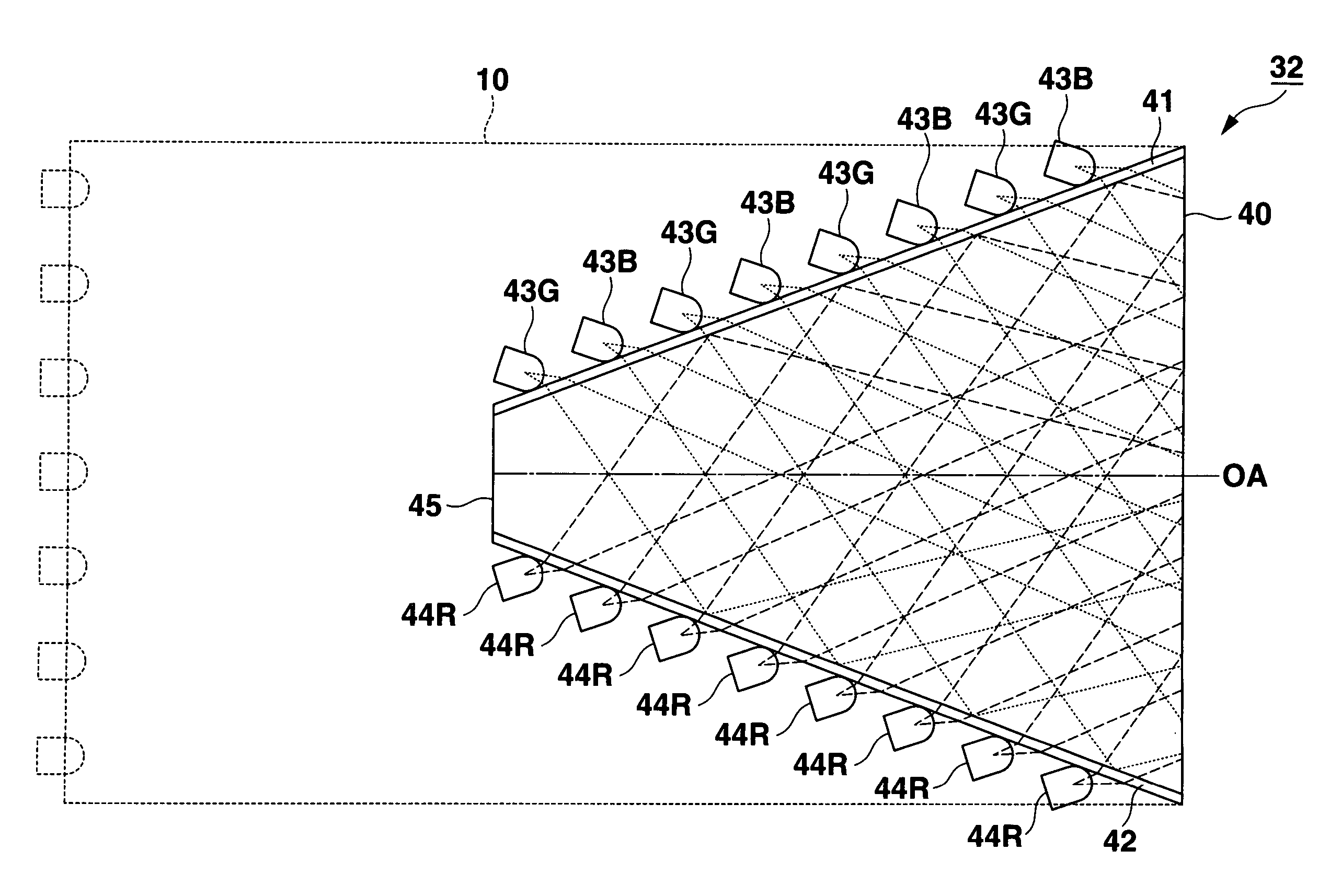
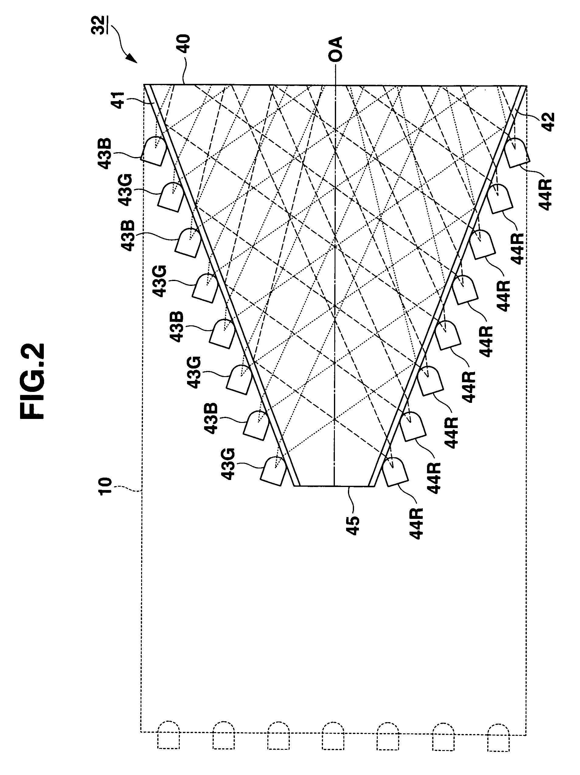
A light source apparatus is provided with a prismoidal light source housing having a first inclined surface formed of a dichroic mirror which transmits light of a wavelength less than 600 nm and reflects light of a wavelength of 600 nm or more, a second inclined surface opposed to the first inclined surface and formed of a dichroic mirror which transmits light of a wavelength of 600 nm or more and reflects a light of a wavelength less than 600 nm, green LEDs and blue LEDs are arranged on an external surface of the first inclined surface, and red LEDs which are arranged on an external surface of the second inclined surface.

Description

CROSS-REFERENCE TO RELATED APPLICATIONS[0001]This application is based upon and claims the benefit of priority from prior Japanese Patent Application No. 2005-146890, filed May 19, 2005, the entire contents of which are incorporated herein by reference.BACKGROUND OF THE INVENTION[0002]The present invention relates to a light source apparatus and a projection apparatus, in particular suitable for a projector apparatus adopting DLP (Registered Trademark) method.[0003]In prior art, projector apparatuses using a discharge lamp such as an ultra-high voltage mercury lamp as a light source are mainstream of projector apparatuses. However, such projector apparatuses have many problems in cost and usability. For example, they consume a large amount of electric power, radiate much heat and causes noises in great deal for cooling. Further, they easily deteriorate despite their expensive prices if their temperatures are not appropriately controlled by proper cooling, and their lives become shor...

Claims


Application Information

Patent Timeline
Patent Type & Authority Patents(United States)
IPC IPC(8): G01N21/55G02B27/14G02B27/18G02F1/13G02F1/133G02F1/13357G03B21/14
CPCG03B21/28H04N9/315H04N9/3152G03B21/2013G03B21/2033G03B21/208
Inventor KUROSAKI, HIDEYUKI
Owner CASIO COMPUTER CO LTD
Learn More