Method of monitoring operation of a disk drive by analyzing the envelope of a read-back signal in the frequency domain

a technology of read-back signal and disk drive, which is applied in the field of disk drive, can solve the problems of inconvenient production-line characterization of disk drive, inconvenient laser doppler vibrometry, and difficult analysis of read-back signal to detect frequency modulation in a digital system

Inactive Publication Date: 2008-03-25
WESTERN DIGITAL TECH INC
View PDF16 Cites 180 Cited by
  • Summary
  • Abstract
  • Description
  • Claims
  • Application Information

AI Technical Summary

Benefits of technology

[0008]In certain embodiments, a method monitors operation of a disk drive. The method comprises providing a disk drive comprising a rotating disk and a head having a read transducer in proximity to a surface of the disk and an adjustment mechanism which controllably adjusts an average relative spacing between the read transducer and the surface. The method further comprises generating a read-back signal by reading from the surface using the read transducer. The read

Problems solved by technology

Laser doppler vibrometry typically utilizes relatively expensive equipment and requires that the disk drive be opened sufficiently to allow a laser beam to reflect from the head.
Each of these factors makes laser doppler vibrometry inconvenient for production-line character

Method used


Image

  • Method of monitoring operation of a disk drive by analyzing the envelope of a read-back signal in the frequency domain
  • Method of monitoring operation of a disk drive by analyzing the envelope of a read-back signal in the frequency domain
  • Method of monitoring operation of a disk drive by analyzing the envelope of a read-back signal in the frequency domain

Examples


Embodiment Construction

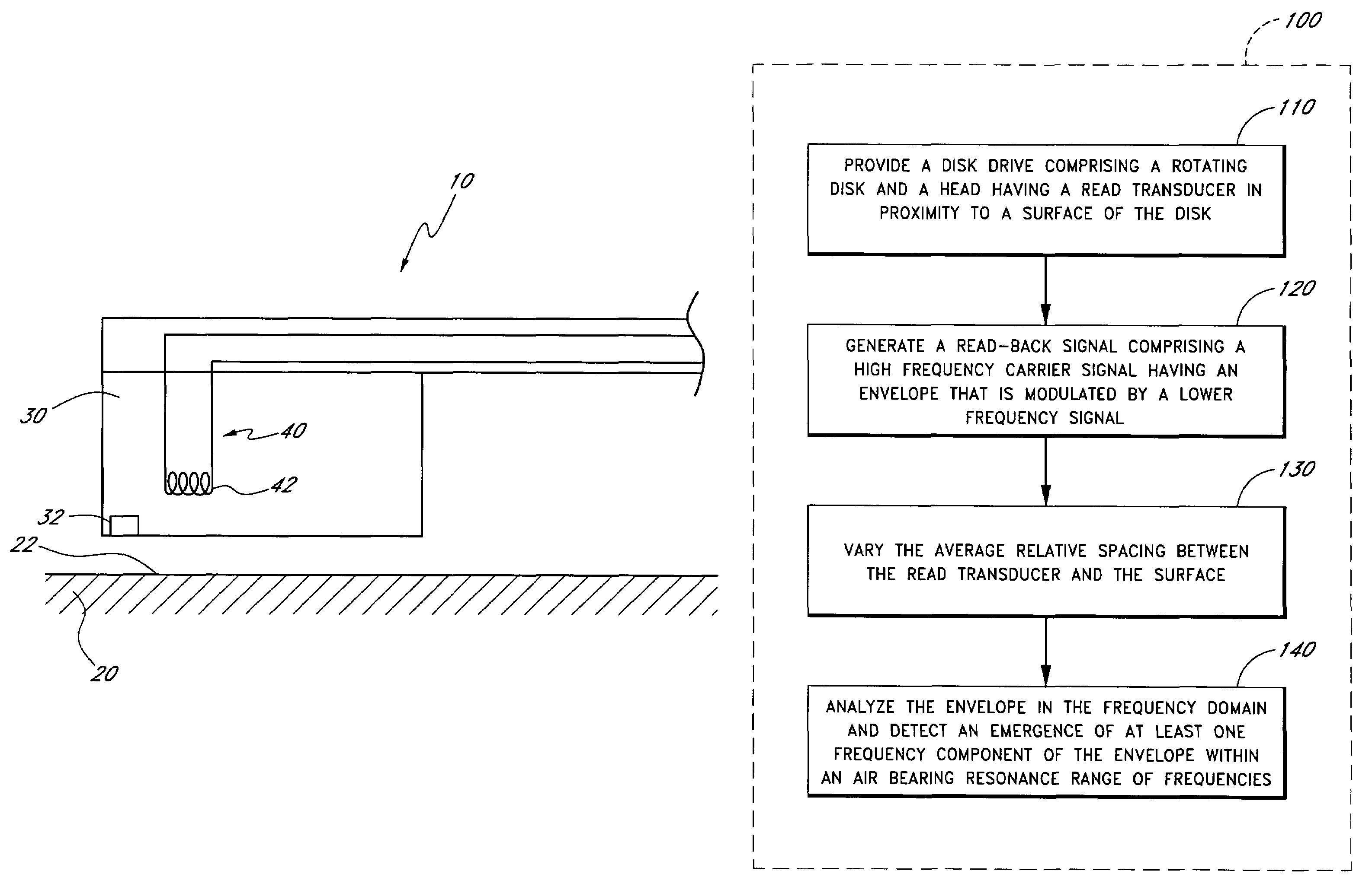
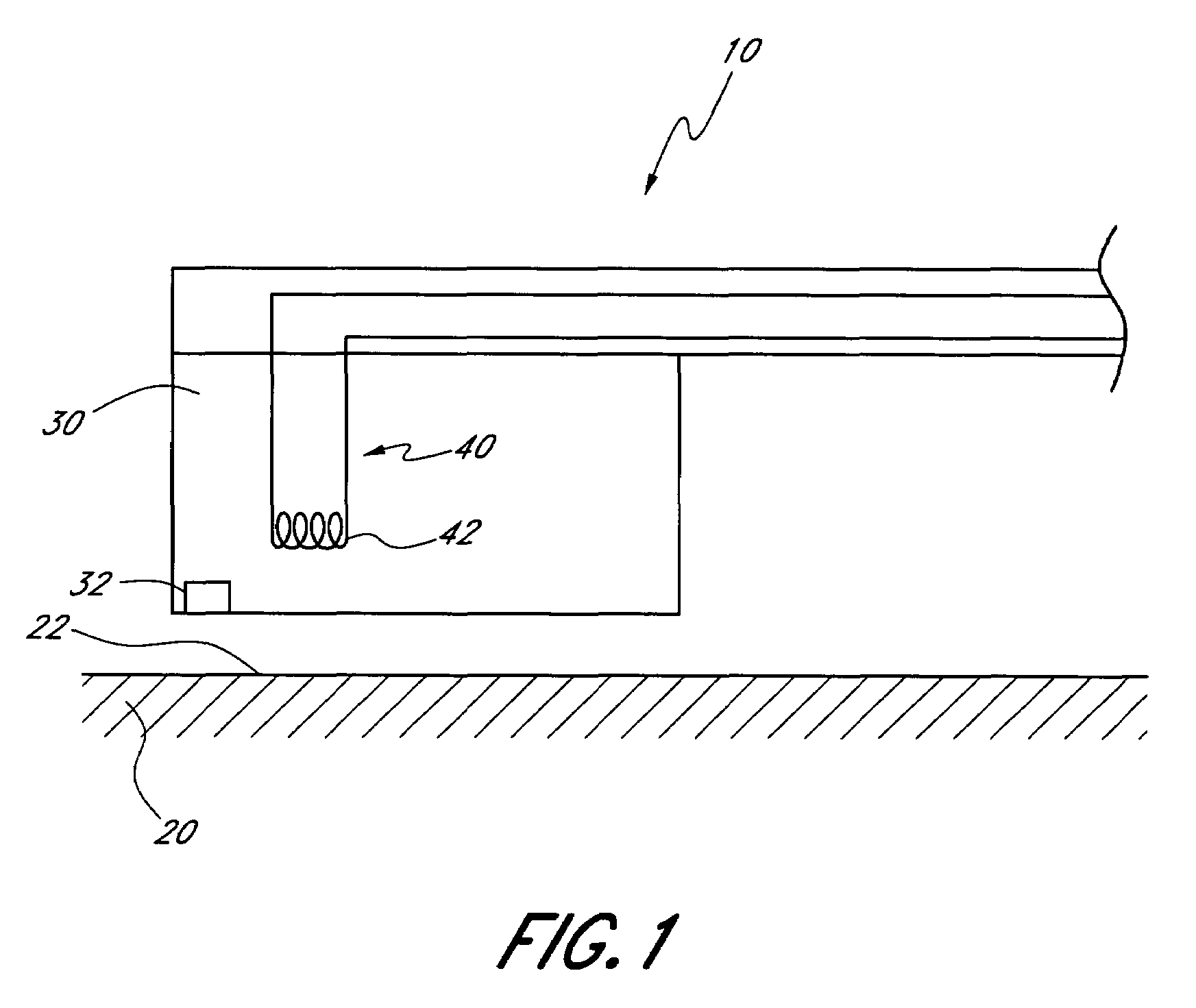
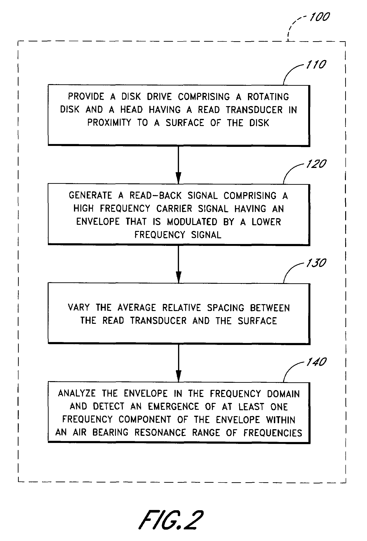
[0017]FIG. 1 schematically illustrates an example disk drive 10 compatible with certain embodiments described herein. FIG. 2 is a flow diagram of an example method 100 of monitoring operation of the disk drive 10 in accordance with certain embodiments described herein. While FIG. 2 and the following description refer to structures shown schematically in FIG. 1, other structures or configurations of the disk drive are also compatible with certain embodiments described herein.

[0018]In certain embodiments, the method 100 comprises providing a disk drive 10, as shown in the operational block 110 of FIG. 2. The disk drive 10 comprises a rotating disk 20 and a head 30 having a read transducer 32 in proximity to a surface 22 of the disk 20. The disk drive 10 further comprises an adjustment mechanism 40 which controllably adjusts an average relative spacing between the read transducer 32 and the surface 22. The read transducer 32 of certain embodiments is part of the head 30 which is proxim...


PUM


Abstract

A method monitors operation of a disk drive. The method includes providing a disk drive which includes a rotating disk and a head having a read transducer in proximity to a surface of the disk and an adjustment mechanism which controllably adjusts an average relative spacing between the read transducer and the surface. The method further includes generating a read-back signal by reading from the surface using the read transducer. The read-back signal includes a high frequency carrier signal having an envelope that is modulated by a lower frequency signal. The method further includes varying the average relative spacing between the read transducer and the surface using the adjustment mechanism. The method further includes analyzing the envelope in the frequency domain and detecting an emergence of at least one frequency component of the envelope within an air bearing resonance range of frequencies.

Description

BACKGROUND OF THE INVENTION[0001]1. Field of the Invention[0002]This invention relates generally to disk drives, and more particularly, to methods of monitoring the operation of disk drives.[0003]2. Description of the Related Art[0004]Disk drives (e.g., hard disk drives) typically utilize a plurality of heads in proximity to magnetic media on a plurality of rotating disks. Each head has a read transducer for reading data from the magnetic media. Each head may also have a write transducer including a pole tip for writing data to the magnetic media.[0005]Generally, higher data storage densities on the magnetic media are obtained by having the read and write transducers close to the magnetic media without touching the magnetic media. The distance between the rotating disk and one or both transducers (referred to as the “flying height” of the head) is typically quite small (e.g., less than one microinch). It is desirable to maintain the flying height at a predetermined level while avoid...

Claims


Application Information

Patent Timeline
IPC IPC(8): G11B21/02G11B27/36
CPCG11B5/6005G11B5/6029G11B5/607
Inventor RUDMAN, VICTORBUTTAR, JAGDEEP S.KHARADY, YOGESH P.PAN, TAO
Owner WESTERN DIGITAL TECH INC
Why Eureka
Try Eureka