Elevator arrangement

a technology for elevators and slats, which is applied in the direction of elevators, building lifts, hoisting equipment, etc., can solve the problems of insufficient room for the toe guard in the low elevator shaft pit, the risk of the person's toe being injured, and the person working on the landing and loading of the elevator, etc., to achieve the effect of reliable and economical safety devices and cost saving

Inactive Publication Date: 2008-04-01
KONE CORP
View PDF10 Cites 9 Cited by
  • Summary
  • Abstract
  • Description
  • Claims
  • Application Information

AI Technical Summary

Benefits of technology

[0008]The object of the present invention is to overcome the above-mentioned drawbacks and to achieve a reliably functioning safety device arrangement of economical cost for the door opening of an elevator, such as a toe guard connected to the elevator safety circuit so that, when the toe guard meets the bottom of a low elevator shaft, the safety circuit of the toe guard will not disconnect the supply of current to the elevator.
[0010]The advantages of the elevator safety device of the invention include good safety and flexible operation in all situations as well as a good tolerance of dirt, allowing reliable operation of the safety device. A further advantage is that the solution of the invention enables a safety circuit without a logic-controlled double switch, so the circuit is simple and economical to implement. In addition, the safety device has a simple structure and allows the use of a toe guard of sufficient height in elevator shafts having a low pit. Moreover, the toe guard is automatically returned to its low position by gravity, thus obviating the need for complicated returning structures or resetting systems. Another advantage is that the toe guard of the invention can be installed on an existing elevator car without dismantling the old threshold structure. For mounting the toe guard, no additional components are needed, but the new toe guard fits directly in the place of the old one. A further advantage is a robust structure having a good tolerance of impacts, as well as the fact that no complex hinged solutions are needed. Yet another advantage is that the solution of the invention also allows the elevator car to be driven as far down as possible during maintenance.

Problems solved by technology

Likewise, without a toe guard there is a risk that a person who is working on a landing and loading or unloading e.g. a freight elevator remaining somewhat above the landing floor may inadvertently get so near the elevator shaft that his toes are in the shaft space.
If the elevator car starts moving downwards in such a situation, there is a risk of the person's toes being injured.
A problem with the use of a toe guard of such a large height is that there is not enough room for the toe guard in a low elevator shaft pit when the elevator car comes e.g. to the lowest level.
One problem is to see to it that the toe guard will not stop the elevator car when the elevator is coming to the lowest landing level in a shaft with a low pit.
One further problem is to bypass the elevator's safety circuit in a way allowing the toe guard to work well as a protective element by stopping the movement of the elevator car if the toe guard hits an obstacle, such as a person's hand, foot or body, but at the same time so that the toe guard will not stop the elevator car when the elevator descends to the lowest level in a shaft with a low pit.
The complex structure is more expensive and is additionally susceptible to damage.
However, the specification does not resent any actual safety circuit or a circuit bypassing it, so there is also the problem that the elevator car will not necessarily stop even if the toe guard should hit an obstacle e.g. at floors other than the bottom floor.
One problem here is that the structure can become dirty, which may prevent the toe guard from being properly returned to the straight position or block the hinges so that the turning movement of the toe guard may become stiff, leading to a risk of breakdown of the whole structure.
A problem with the solution described in this specification is dirt, which can easily get into the open spaces between the moving parts, causing operational disturbances.
This solution, too, has the drawback that it does not propose any kind of safety circuit, so there not necessarily anything to stop the elevator when the toe guard hits an obstacle.

Method used


Image

  • Elevator arrangement
  • Elevator arrangement
  • Elevator arrangement

Examples


Embodiment Construction

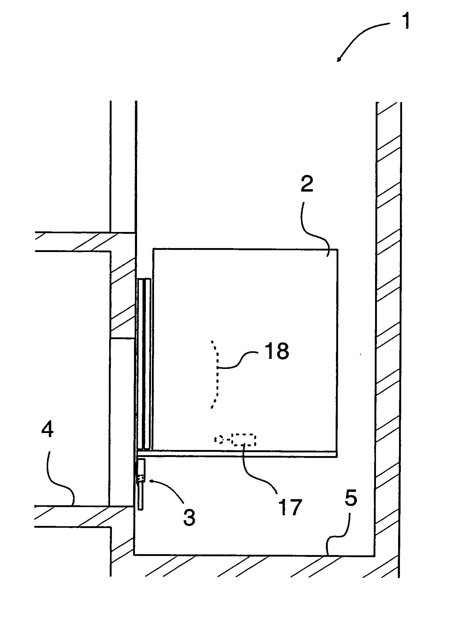
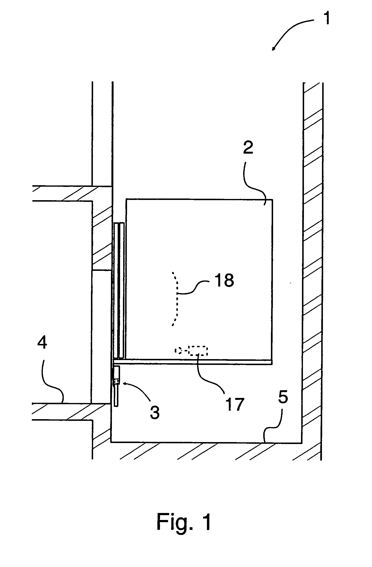
[0037]FIG. 1 presents a diagrammatic and simplified view of an elevator car 2 having stopped in the elevator shaft 1 at a position somewhat above the lowest landing floor 4. In the doorway, the gap opening into the elevator shaft between the lower edge of the elevator car and the landing floor 4 is covered by telescoping toe guard 3 extending downwards from the front edge of the elevator car 2 and having a total height larger than the height of the pit 5 of the elevator shaft.

[0038]Thus, people getting out of the elevator car having stopped in an exceptional position can not fall accidentally into the elevator shaft. On the bottom floor, such a fall is not as dangerous as in a similar situation on upper floors. FIG. 1 also shows a safety circuit bypass switch 17, depicted with broken lines and, in this embodiment, fastened to the lower part of the elevator car 2. The switch is controlled by a ramp 18 mounted on a side wall of the shaft 1.

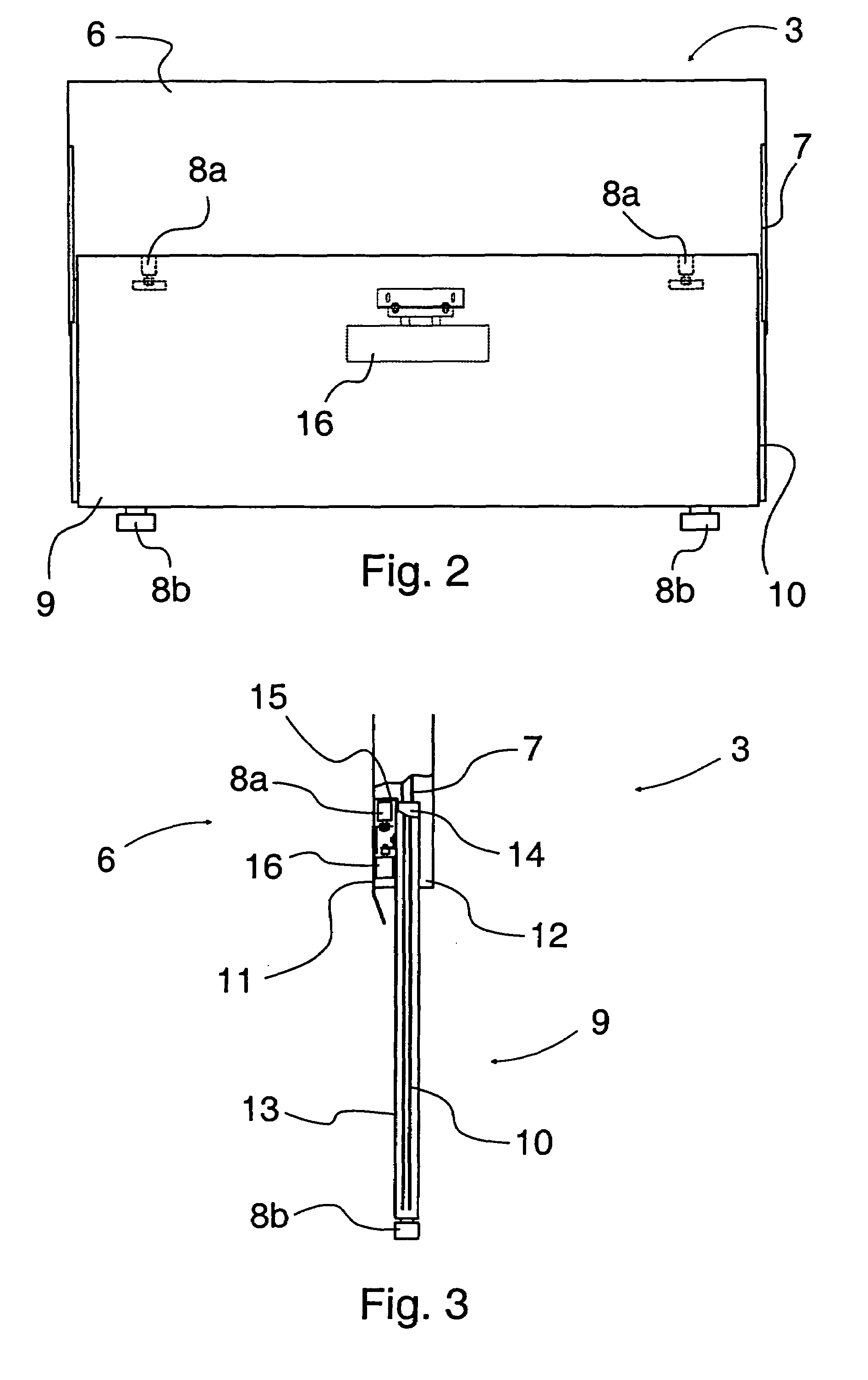
[0039]FIGS. 2 and 3 present a toe guard 3 acc...


PUM


Abstract

The invention relates to a safety device arrangement for an elevator door opening, said safety device arrangement comprising at least a toe guard (3) placed substantially at the lower edge of the elevator car and a safety circuit (21) connected to the elevator system. The safety device arrangement comprises a safety circuit switch (16) placed on the toe guard (3) and a bypass switch (17) connected to the safety circuit (21), said bypass switch being fitted to bypass the safety circuit switch (16) at least when the elevator is at or close to the lowest landing floor.

Description

FIELD OF THE INVENTION[0001]This application is a Continuation of co-pending PCT International Application No. PCT / FI2005 / 000229 filed on May 18, 2005, which designated the United States, and on which priority is claimed under 35 U.S.C. § 120. This application also claims priority under 35 U.S.C. § 119(a) on Patent Application No. 20040777 filed in Finland on Jun. 7, 2004. The entire contents of each of the above documents is hereby incorporated by reference.BACKGROUND OF THE INVENTION[0002]The present invention relates to a safety arrangement for an elevator door opening.[0003]A safety device used in an elevator door opening is a foot guard, also called a toe guard, placed at the lower edge of the elevator car and having a length substantially at least equal to the width of the landing door opening. The toe guard is a plate-like piece or equivalent mounted in a substantially vertical plane, and it is designed to block the gap opening into the elevator shaft between the lower edge o...

Claims


Application Information

Patent Timeline
Patent Type & Authority Patents(United States)
IPC IPC(8): B66B13/28B66B1/28B66B5/16B66BB66B5/02
CPCB66B13/285
Inventor KETONEN, ARIKETOVIITA, SEPPOVAINIO, VELI-MATTI
Owner KONE CORP
Why Eureka
Try Eureka