
Methods and apparatus for controlling rotational speed of a rotor

a technology of rotational speed and rotor blade, which is applied in the field of rotors, can solve the problems of increasing the torque required by the pitch drive motor, increasing the friction within the pitch drive system, and unable to accurately control the pitch of the rotor blade, so as to achieve the effect of constant rotational speed of the rotor

Active Publication Date: 2008-04-01
GE INFRASTRUCTURE TECH INT LLC
View PDF25 Cites 76 Cited by
  • Summary
  • Abstract
  • Description
  • Claims
  • Application Information

AI Technical Summary

Problems solved by technology

However, as rotor diameter and therefore rotor blade lengths increase, friction within the pitch drive system may also increase, which may increase the torque required by the pitch drive motor to pitch the rotor blades.
Moreover, as rotor blade lengths increase it may also be more difficult to accurately control the rotor blade pitch because of increased gear backlash within the pitch drive system.
As such, the pitch drive system may be required to perform more pitching operations to accurately control the angle of the rotor blades, which may increase parasitic power loses within the wind turbine and / or may increase an amount of cooling required by the pitch drive system to prevent damage thereto and / or failure thereof.
Moreover, pitching the rotor blades may increase loads induced to a tower of the wind turbine due to the effect of blade pitch on rotor thrust.

Method used


Image

  • Methods and apparatus for controlling rotational speed of a rotor
  • Methods and apparatus for controlling rotational speed of a rotor
  • Methods and apparatus for controlling rotational speed of a rotor

Examples


Embodiment Construction

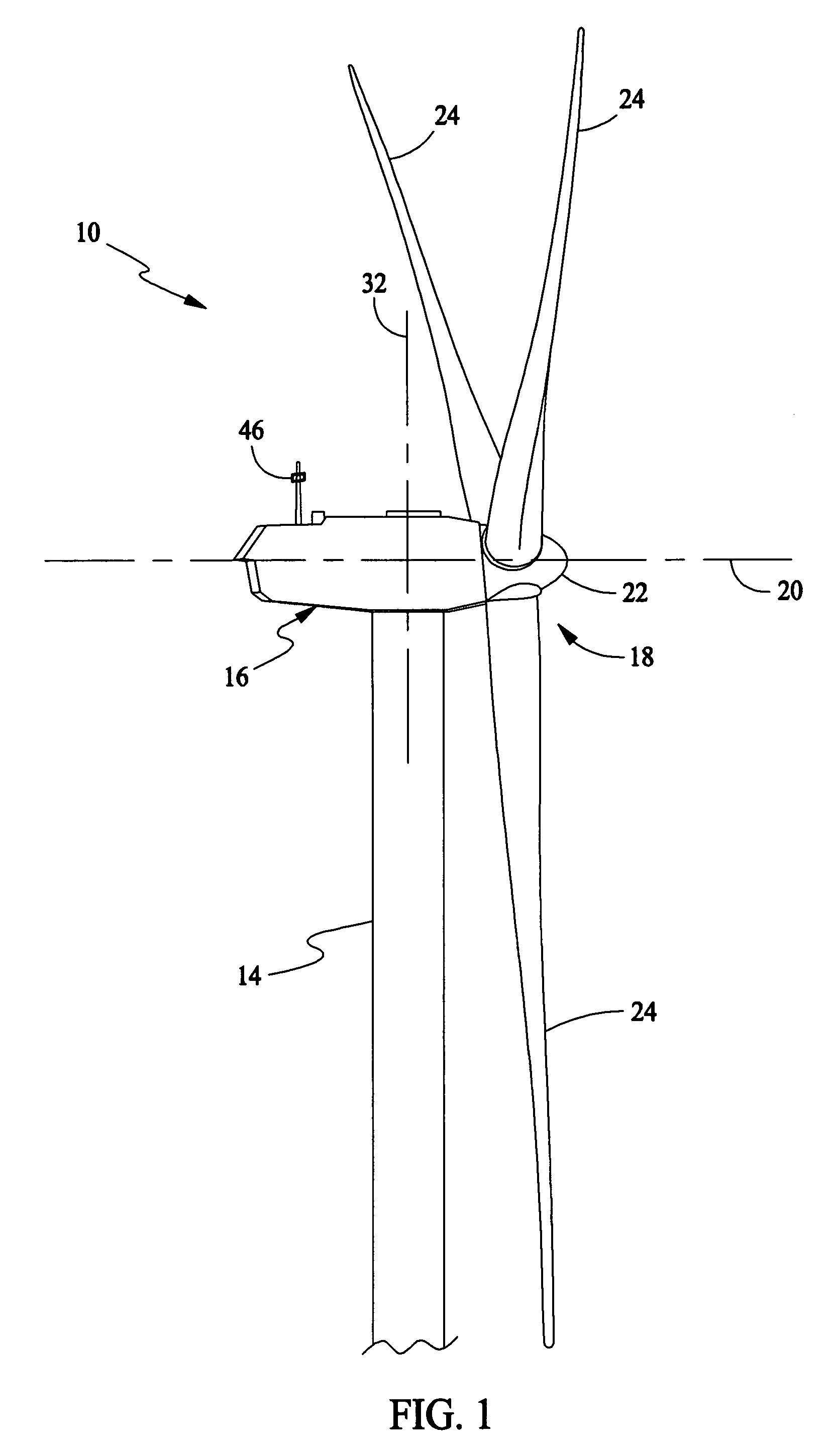
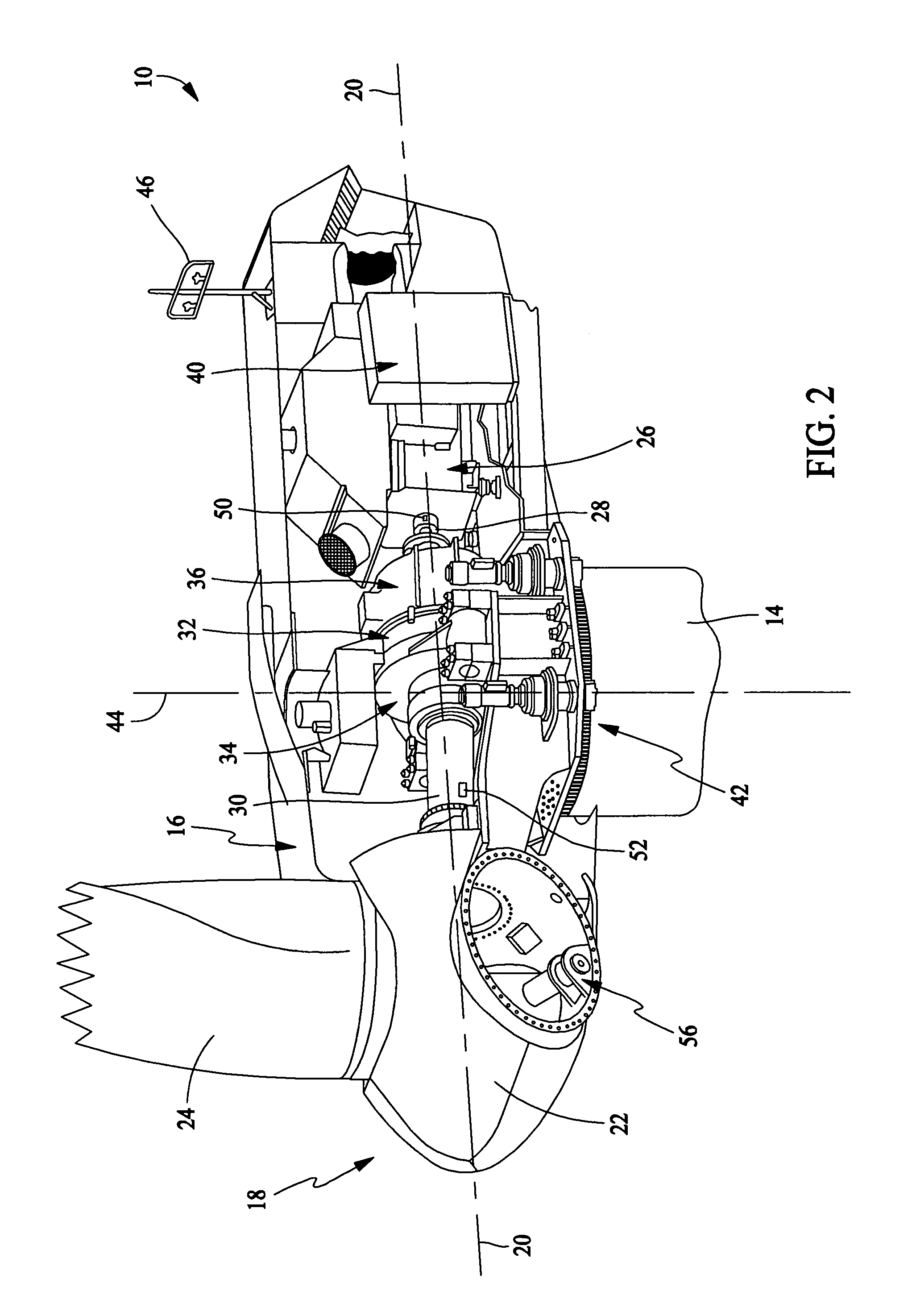
[0011]As used herein, the term “blade” is intended to be representative of any device that provides reactive force when in motion relative to a surrounding fluid. As used herein, the term “wind turbine” is intended to be representative of any device that generates rotational energy from wind energy, and more specifically, converts kinetic energy of wind into mechanical energy. As used herein, the term “wind generator” is intended to be representative of any wind turbine that generates electrical power from rotational energy generated from wind energy, and more specifically, converts mechanical energy converted from kinetic energy of wind to electrical power. As used herein, the term “windmill” is intended to be representative of any wind turbine that uses rotational energy generated from wind energy, and more specifically mechanical energy converted from kinetic energy of wind, for a predetermined purpose other than generating electrical power, such as, but not limited to, pumping a...


PUM


Abstract

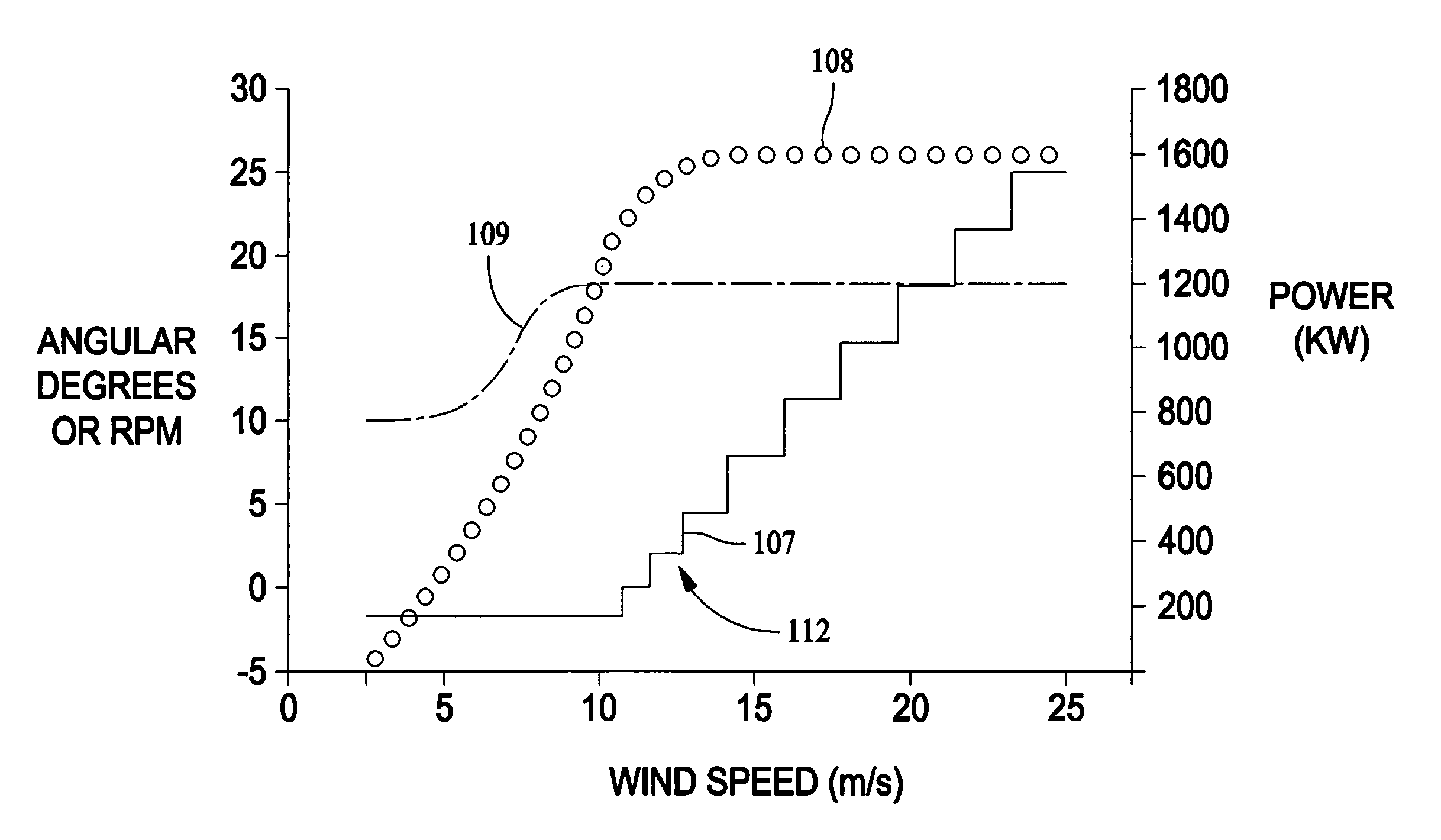
A method for controlling a rotational speed of a rotor having at least one rotor blade, a rotor shaft, and an electrical generator coupled thereto. The method includes controlling a torque of the rotor shaft by controlling a torque of the electrical generator, alternating between changing an angle of pitch of the at least one rotor blade and maintaining the angle of pitch of the at least one rotor blade substantially constant, and maintaining a substantially constant rotational speed of the rotor during variable wind speeds above a predetermined rated wind speed.

Description

BACKGROUND OF THE INVENTION[0001]This invention relates generally to rotors, and more specifically to methods and apparatus for controlling the rotational speed of a rotor.[0002]During operation of at least some known wind turbines, rotor speed is controlled to prevent the wind turbine rotor from rotating at or above a predetermined speed that may damage components of the wind turbine. For example, at least some known wind turbines control rotor speed by pitching the rotor blades using a pitch drive system that changes an angle of the rotor blades, thereby changing the aerodynamic torque of the rotor. Since their introduction, wind turbines have continuously increased in physical size and electrical power output. However, as rotor diameter and therefore rotor blade lengths increase, friction within the pitch drive system may also increase, which may increase the torque required by the pitch drive motor to pitch the rotor blades. Moreover, as rotor blade lengths increase it may also ...

Claims


Application Information

Patent Timeline
Patent Type & Authority Patents(United States)
IPC IPC(8): F03D7/00
CPCF03D7/0224F03D7/0272F03D7/0276F03D7/042F03D7/06Y02E10/725F05B2220/7066F05B2260/76F05B2270/1014F05B2270/32Y02E10/72Y02E10/74
Inventor WILLEY, LAWRENCE DONALDCUNNINGHAM, JOHN NOELGEBHARDT, ERICUPHUES, ULRICHHOLLEY, WILLIAM EDWINPIERCE, KIRK GEE
Owner GE INFRASTRUCTURE TECH INT LLC
Learn More