IC tag mounting on a harness and harness mounting method

a technology of ic tag and mounting method, which is applied in the direction of coupling device connection, way, instruments, etc., can solve the problems of inconvenient use and inability to read information stored in the tag chip, and achieve the effect of simple checking

Inactive Publication Date: 2008-04-01
HITACHI LTD
View PDF6 Cites 54 Cited by
  • Summary
  • Abstract
  • Description
  • Claims
  • Application Information

AI Technical Summary

Benefits of technology

[0003]The present invention relates to an IC tag mounting for a harness which mounts a wireless IC tag to transmit information recorded in an IC chip from an antenna in a wireless form, and a harness mounting method for mounting this IC tag-mounted harness on an electrical apparatus.

Problems solved by technology

In the technique disclosed in JP-A-2004-152543, however, there is a drawback that the information stored in the tag chip cannot be read unless the reader / writer is within an extremely short distance from the antenna, although there is an advantage that the information stored in the tag chip does not leak to the outside.
For example, when reading information stored in the tag chip and checking whether one of the connectors is fitted into the other normally, the reader / writer must be brought into an extremely short distance from the antenna and the fitting state must be inspected, resulting in a problem of being inconvenient to use.

Method used


Image

  • IC tag mounting on a harness and harness mounting method
  • IC tag mounting on a harness and harness mounting method
  • IC tag mounting on a harness and harness mounting method

Examples


first embodiment

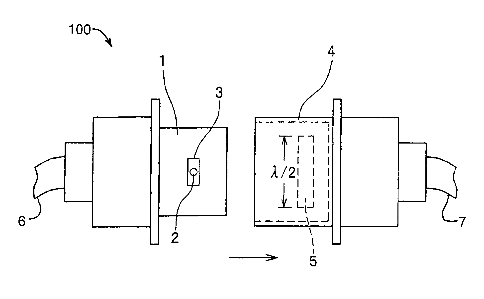
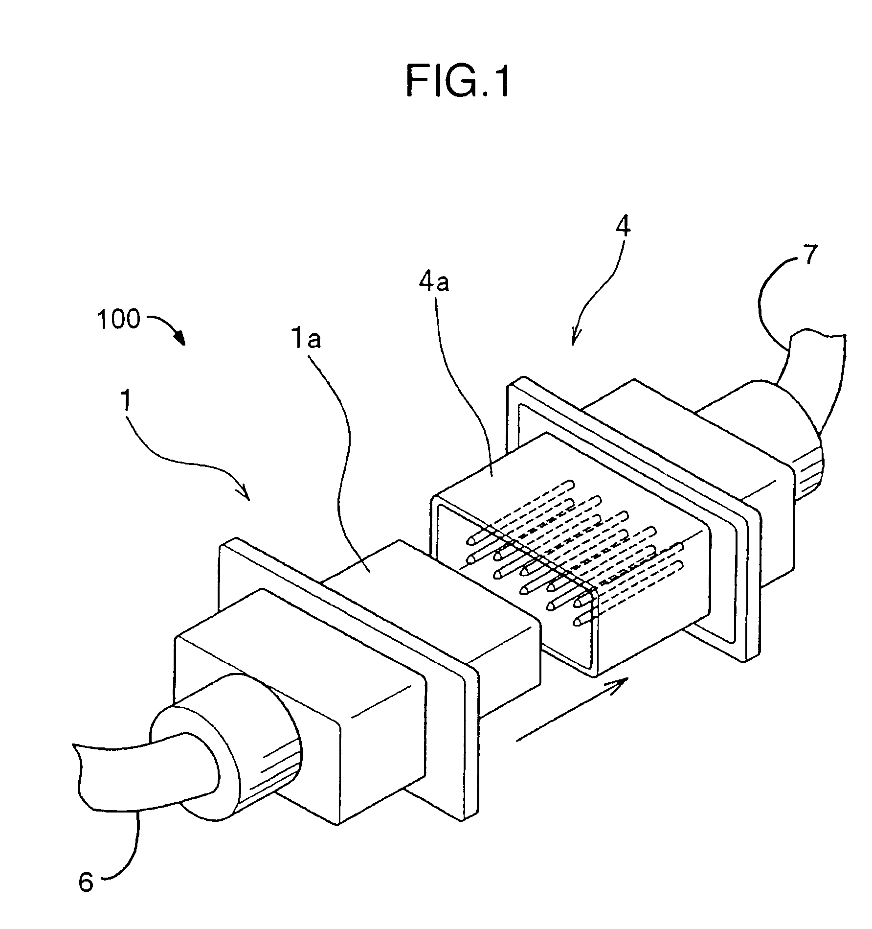
[0021]FIG. 1 is a diagram showing connector portions of the wire harness 100 used in the present embodiment. A male connector 1 includes an insertion end 1a. A female connector 4 includes an accepting frame 4a. When the insertion end 1a of the male connector 1 is inserted into the accepting frame 4a in an insertion direction indicated by an arrow as far as a bottom of the accepting frame 4a, connection in the wire harness is conducted, whereby one or more first electrical members 6 are electrically connected to one or more second electrical members 7. At this time, a predetermined gap is formed between an outside periphery face of the insertion end 1a and an inside periphery face of the accepting frame 4a.

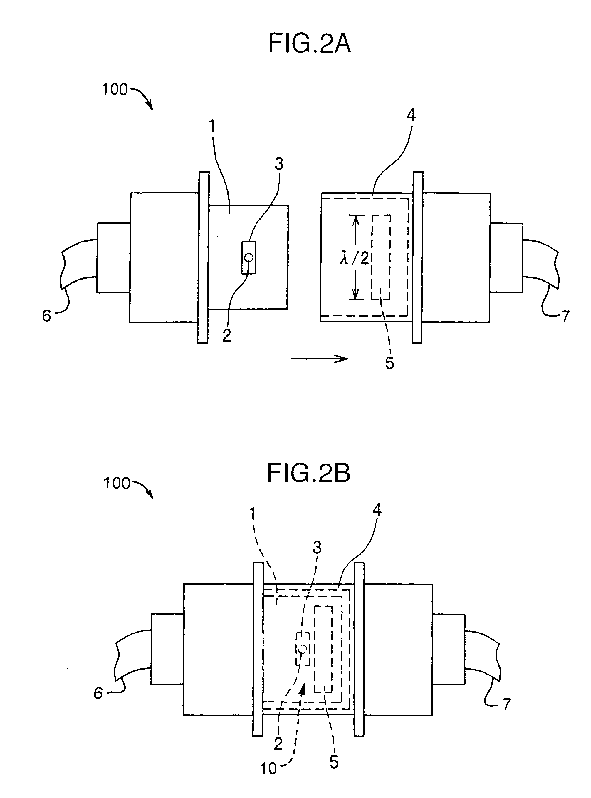
[0022]FIGS. 2A-2B are schematic configuration diagrams of an IC tag mounting on harness 100 in the present embodiment, in which FIG. 2A shows a state before fitting, and FIG. 2B shows a state after fitting. In the ensuing description, the surface of the insertion end 1a of the mal...

second embodiment

[0028]FIGS. 3A-3B are schematic configuration diagrams of an IC tag 18 mounting on a harness200 in a second embodiment, in which FIG. 3A shows a state before fitting, and FIG. 3B shows a state after fitting. As shown in FIG. 3A, a minute antenna 13 having an IC chip 12 placed nearly on the center thereof and an ordinary antenna 15 having an IC chip 14 placed nearly on the center thereof are mounted on the surface of the male connector 1 included in the harness 200 so as to be parallel to each other. Each of the IC chip 12 and the IC chip 14 is housed in a small package that has, for example, a width of approximately 0.4 mm, a depth of approximately 0.4 mm, and a height of approximately 0.1 mm. Various kinds of information concerning the wire harness are previously recorded in the IC chip 12 and the IC chip 14.

[0029]The minute antenna 13 is so small that it can transmit only a weak radio wave in the same way as the first embodiment. For example, the minute antenna 13 has a size that ...

third embodiment

[0039]In a third embodiment, a method of preventing false fitting of connectors when a plurality of wire harnesses are included and connectors having the same shape are used will now be described. FIGS. 5A-5C are concept diagrams showing states in which wireless IC tags are mounted respectively so as to be associated with fitting purposes in wire harnesses having the same shape. In the case of an A-type harness 300, an IC chip 23 having a minute antenna is mounted on a forefront portion of the male connector 1 as shown in FIG. 5A. An antenna (auxiliary antenna) 24 is mounted in a position (i.e., the interior part) deviated at spacing of, for example, 0.5 mm from the minute antenna of the IC chip 23 on the female connector 4 so as to be able to receive a radio wave from the minute antenna of the IC chip 23. In FIG. 5A, an antenna 24, the IC chip 23, and its minute antenna are shown in the overlapped state for convenience. When the male connector 1 is fitted into the female connector ...


PUM


Abstract

An IC chip and a minute antenna for conducting transmission with a weak radio wave are mounted on a male connector. An auxiliary antenna for amplifying the weak radio wave emitted by the minute antenna and transmitting the amplified radio wave is mounted on a female connector. If the male connector is fitted into the female connector normally, then the distance between the minute antenna and the auxiliary antenna becomes 1.0 mm or less, and consequently the weak radio wave transmitted by the minute antenna is amplified by the auxiliary antenna and transmitted to the outside. Unless fitting is conducted normally, then the distance between the minute antenna and the auxiliary antenna becomes longer than 1.0 mm, and consequently the weak radio wave emitted the minute antenna is not amplified and transmitted. By receiving the information stored on the IC chip, the fitting state of the connectors can be checked.

Description

INCORPORATION BY REFERENCE[0001]The present application claims priority from Japanese application JP 2004-256654 filed on Sep. 3, 2004, the content of which is hereby incorporated by reference into this application.BACKGROUND OF THE INVENTION[0002]1. Field of the Invention[0003]The present invention relates to an IC tag mounting for a harness which mounts a wireless IC tag to transmit information recorded in an IC chip from an antenna in a wireless form, and a harness mounting method for mounting this IC tag-mounted harness on an electrical apparatus.[0004]2. Description of the Related Art[0005]In recent years, wireless IC tags are used vigorously to confirm articles or confirm fitting states of articles. For example, JP-A-2004-152543 discloses a technique for mounting a wireless IC tag on a connector, reading information in the connector, and sensing the fitting state of the connector. This technique is constructed to mount a tag chip including an IC chip and a minute antenna on a ...

Claims


Application Information

Patent Timeline
Patent Type & Authority Patents(United States)
IPC IPC(8): G08B13/14
CPCG06K7/10178G06K19/07758H01R13/465H01R13/641B61B1/02E01F1/00E05Y2900/404E06B11/025E05F15/668
Inventor SAKAMA, ISAOASHIZAWA, MINORU
Owner HITACHI LTD
Why Eureka
Try Eureka