
Non-destructive inspection of material in container

a container and non-destructive technology, applied in the direction of measuring devices, instruments, scientific instruments, etc., can solve the problems of limited product inspection, less than optimal inspection form, and each of these devices has its own inherent limitations

Inactive Publication Date: 2007-01-16
METTLER TOLEDO INC
View PDF4 Cites 102 Cited by
  • Summary
  • Abstract
  • Description
  • Claims
  • Application Information

AI Technical Summary

Benefits of technology

The patent describes an apparatus and method for inspecting materials in containers using X-ray beams. The method involves positioning X-ray beam emitter and detector on either side of a conveyor where the materials are conveyed. By using two X-ray apparatus located on opposite sides of the conveyor, the method improves the image of the bottom crown of a container. The two X-ray beams on each side of the conveyor are angled at 45 degrees with respect to each other. The technical effect of this invention is to provide a non-destructive inspection method for materials in containers that allows for better visualization of the bottom part of the container.

Problems solved by technology

Traditionally, product inspection has been limited to physical inspection of the product by a worker on the production line.
Obviously, this form of inspection is less than optimal.
Each of these devices has its own inherent limitations, and even the system in combination lacked the ability to provide much information.
A problem encountered when using such apparatus and systems, especially when inspecting food in containers, is that the geometry of the containers often causes undue lines in detector images thereof, which detract from the quality of such images and, therefore, negatively affect interpretations of the images.
None of the apparatus and methods described in the above-mentioned patents adequately overcomes this problem.
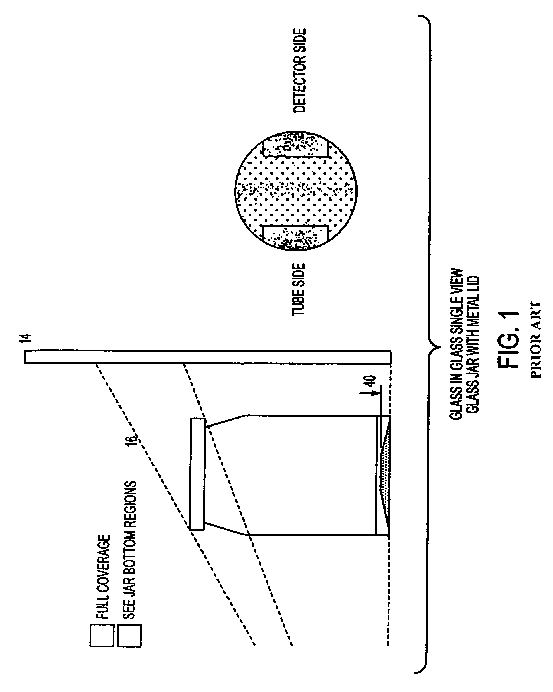
X-ray inspection of food products in glass jars to eliminate broken glass contaminants presents a unique challenge due to the crown typically found in the jar bottom.
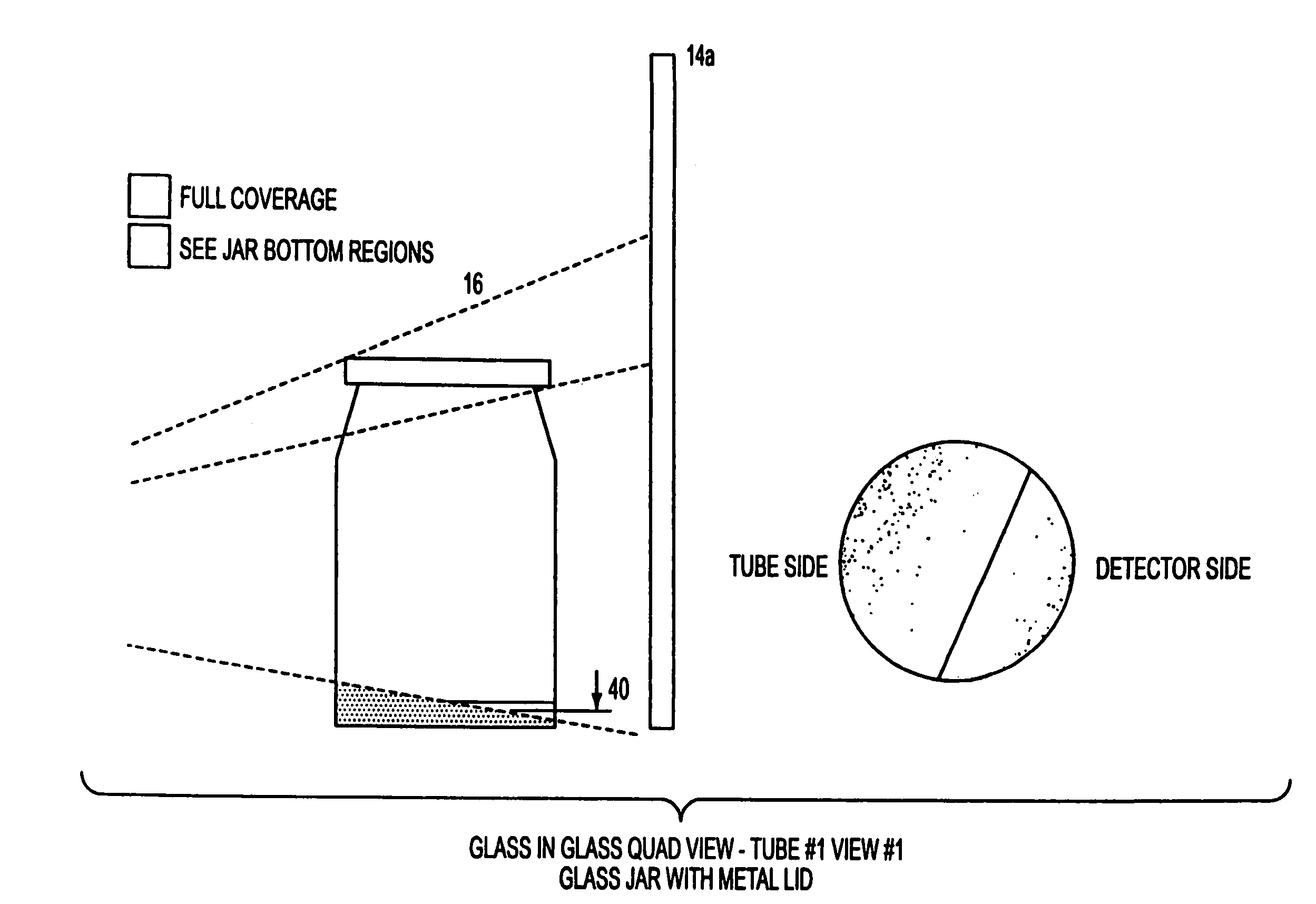
Single view systems are offered but the coverage on the jar bottom is limited as this crown will “hide” the contaminant resulting in the fact that the contaminant must be of a size large enough to extend above the crown as viewed by the x-ray system.

Method used


Image

  • Non-destructive inspection of material in container
  • Non-destructive inspection of material in container
  • Non-destructive inspection of material in container

Examples


Embodiment Construction

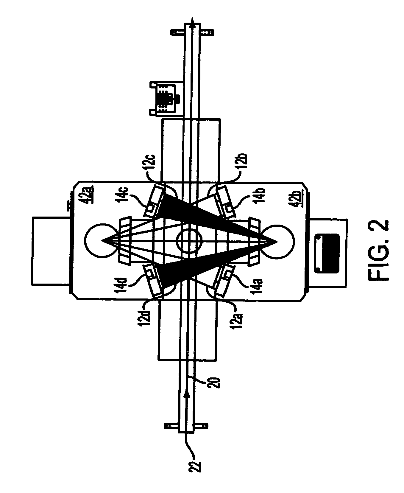
[0021]The present invention provides a system and method which eliminate the “hidden” areas of the prior art systems by orienting the x-ray beams to be parallel to the slope of a crown 10 in the container 16. In one embodiment illustrated in FIG. 2, system has a structure of two x-ray apparatus 42a and 42b oriented on opposite sides of the conveyor 20 traveling through the system. Each apparatus emits a dual beam at 45° from one and other. Four x-ray sensor devices 14a, 14b, 14c, 14d are placed on the opposite side of the conveyor from their respective tube. This inspection structure with two dual beam tubes and four sensors allows substantially 100% inspection of the glass jar bottom.

[0022]FIG. 1 depicts the area of a crown 40 detected by an apparatus of the prior art. The prior art apparatus does not provide adequate detection as it is capable of detecting only a small portion of the area below the crown 40, and the angle of crown creates difficulty in obtaining a clean image of e...


PUM

PropertyMeasurementUnit
angleaaaaaaaaaa
heightaaaaaaaaaa
heightaaaaaaaaaa

Abstract

An apparatus and method for non-destructive inspection of materials housed in containers involves orienting an X-ray beam emitter and detector to direct and detect an X-ray beam at an angle substantially parallel to a sloped surface of the container to be inspected. A first X-ray apparatus is located opposite a second X-ray apparatus, and both the first and second X-ray apparatus are adapted to provide two X-ray beams. This arrangement provides for imaging of the entire area of a sloped portion of the container without any shadow or hidden spots.

Description

CROSS-REFERENCE TO RELATED PATENT APPLICATIONS[0001]This application is a continuation-in-part of U.S. patent application Ser. No. 10 / 629,868, which was filed on Jul. 30, 2003 now U.S. Pat. No. 6,895,072, and is accordingly entitled to the benefit of and priority to U.S. Provisional Application 60 / 457,319. Both of the aforementioned applications are incorporated by reference herein.BACKGROUND OF THE INVENTION[0002]This invention concerns the non-destructive inspection of materials housed in containers, and more specifically the inspection of such materials using X-ray beams.[0003]Inspection of various production products has become increasingly important in recent years. Traditionally, product inspection has been limited to physical inspection of the product by a worker on the production line. Obviously, this form of inspection is less than optimal. As such, two more useful devices were developed and became the standard inspection apparatus: a check weigher and a metal detector. Eac...

Claims


Application Information

Patent Timeline
Patent Type & Authority Patents(United States)
IPC IPC(8): G01N23/04G01N23/00
CPCG01N23/10G01N23/00G01N23/083
Inventor NABORS, JAMESNASH, BROOKSCHROCK, TODDWYMAN, DICKHARTWIG, NORBERTSMITH, EARLWILLIAMSON, ADAM
Owner METTLER TOLEDO INC
Learn More