Robotic vehicle with deduced reckoning positioning system

a technology of deduced reckoning and positioning system, which is applied in the direction of automatic actuation, process and machine control, instruments, etc., can solve the problems of increasing the difficulty of modelling, affecting the performance of the vehicle, and affecting the stability of the vehicle,

Inactive Publication Date: 2000-04-04
ST ENG AETHON INC
View PDF19 Cites 102 Cited by
  • Summary
  • Abstract
  • Description
  • Claims
  • Application Information

AI Technical Summary

Problems solved by technology

Furthermore, slippage between the respective wheels and the flooring is inevitable.
The slippage of the wheels is a result of the side forces generated on the wheels of the vehicle.
The larger, and more difficult to model, resistance associated with wheeled vehicles is that of a third or fourth point of contact between the vehicle and the floor which can exert forces in any direction on the powered wheel.
Robotic vehicles utilizing ded-reckoning as positioning systems have not satisfactorily eliminated wheel slippage, resulting in unacceptable error in the ded-reckoning positioning or tracking system.
Consequently, the prior art robotic vehicles required frequent landmarks or methods of updating the position.

Method used


Image

  • Robotic vehicle with deduced reckoning positioning system
  • Robotic vehicle with deduced reckoning positioning system
  • Robotic vehicle with deduced reckoning positioning system

Examples


Embodiment Construction

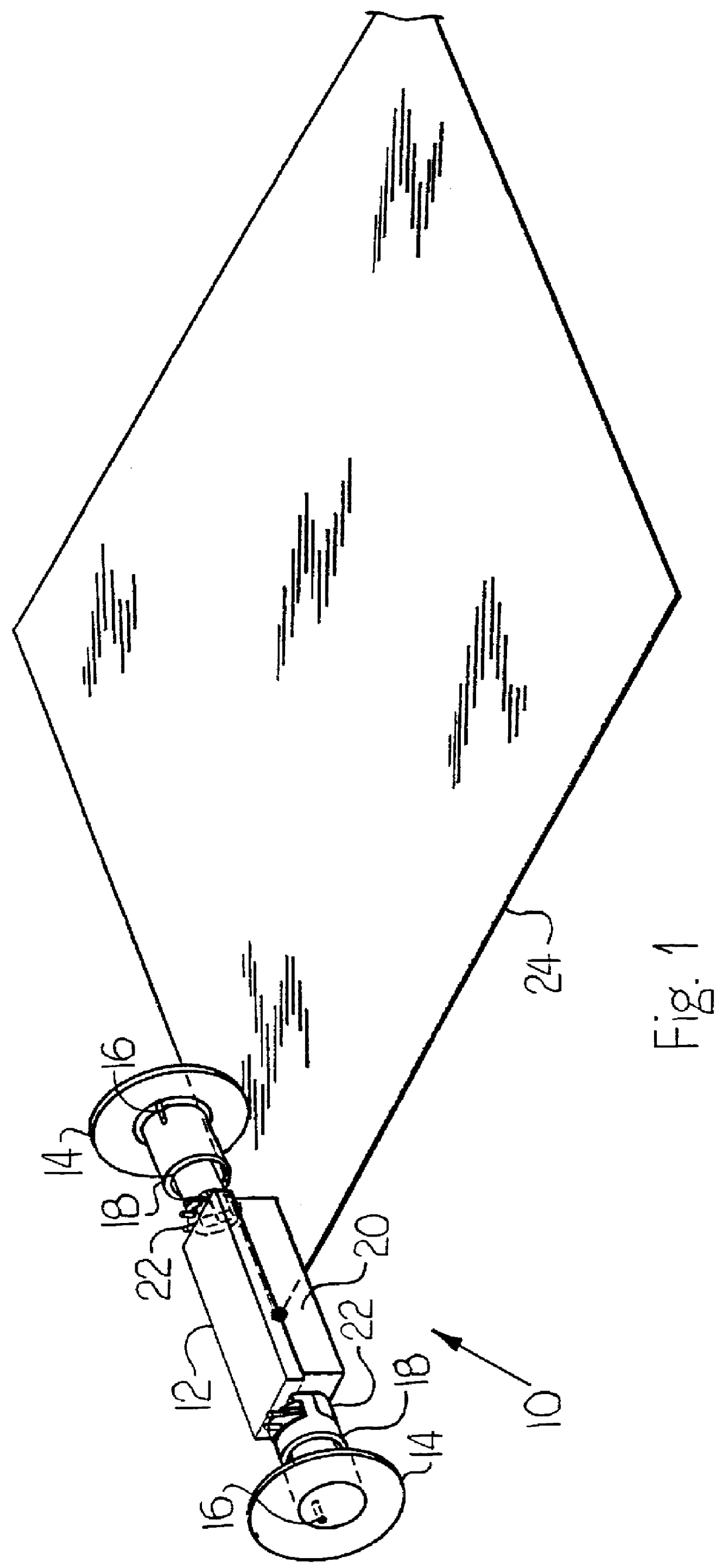
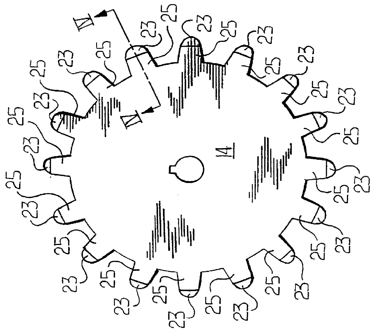
FIG. 1 schematically illustrates a robotic vehicle 10 according to the present invention, which is shown in perspective in FIGS. 6 and 7. The robotic vehicle 10 includes a main body portion 12 suspended between a pair of axially colinear wheels 14. Each wheel 14 includes an independent axle 16 moveable by an independent motor 18 supported on the body 12. Each motor 18 is operable by a central controller 20 supported on the main body 12 of the robotic vehicle 10. Additionally, an encoder 22 is associated with each motor 18 and is connected to the controller 20. Each encoder 22 calculates the degree of rotation imparted by the motor 18 on each axle 16. FIG. 1 additionally illustrates a reference plane 24 within which the controller 20 will maintain the relative position and orientation of the robotic vehicle 10 through ded-reckoning techniques as will be described hereinafter.

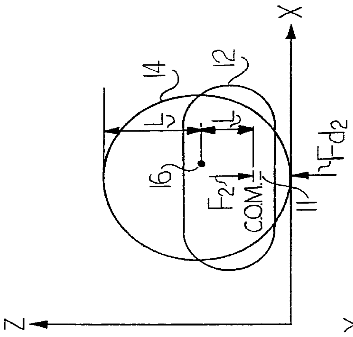
FIG. 2 schematically illustrates a side view of the robotic vehicle 10 which utilizes the two axially colinear...


PUM


Abstract

A robotic vehicle includes two independent axially colinear wheels, wherein the wheels form the only contact with the floor when the robotic vehicle is at rest. A robot body is mounted between the wheels, and a ded-reckoning positioning system is mounted on the robot body. Each wheel includes a series of circumferentially spaced points forming the surface contact of said wheel with the floor. A graphical user interface is provided for manipulating the robotic vehicle. A robot attaching harness is on the robot body for coupling auxiliary equipment to the robotic vehicle. The ded-reckoning positioning system updates the relative position and orientation of the robotic vehicle through measurement of wheel rotation, and calculates an amount of slip for each wheel.

Description

1. Field of the InventionThe present invention relates to a robotic vehicle with a vehicle tracking system, more specifically, the present invention relates to a suspended carriage system for improved ded-reckoning of robotic vehicles.2. Background InformationDed-reckoning, often called dead-reckoning in error, is a shortening of the term deduced reckoning. Deduced reckoning refers to a guidance or navigational system used to calculate the position of a moving object. Originally, sailors used to calculate their position by knowing where they started, and knowing the direction and the speed at which they were traveling. Deduced reckoning is the calculating of the current or updated position of an object based upon factors associated with movement of the object such as the direction of travel, the speed of travel and the time spent traveling in specific directions. The resulting calculated current position of the object is an approximation, and occasional corrections are made based up...

Claims


Application Information

Patent Timeline
Patent Type & Authority Patents(United States)
IPC IPC(8): B25J5/00G05D1/02
CPCG05D1/0272B25J5/007
Inventor THORNE, HENRY F.
Owner ST ENG AETHON INC
Why Eureka
Try Eureka