Variable clocked scan test improvements

a technology of deterministic tests and scans, applied in error detection/correction, program control, instruments, etc., can solve the problems of reducing the computation time to arrive at a compressed solution, and reducing the computation time required to achieve the compression of test patterns. , to achieve the effect of limiting the clocking overhead of deterministic tests and reducing the number of required shifts

Inactive Publication Date: 2008-04-01
INTELLECTUAL VENTURES I LLC
View PDF6 Cites 25 Cited by
  • Summary
  • Abstract
  • Description
  • Claims
  • Application Information

AI Technical Summary

Benefits of technology

[0005]The test logic structure shown in FIG. 1, is described in U.S. patent application Ser. No. 10 / 351,276. U.S. patent application Ser. No. 10 / 750,949 presents a reverse symbolic simulation to compress test patterns that are applied to structures such as the one shown in FIG. 1. The simulation starts with the required state and simulates in reverse time to determine the compressed input states necessary to meet those required states. In this case variables are introduced or added to existing expressions on both inputs of exclusive-or gates as the required values pass through the gates in during each reverse shift. In other words, if the required value was a 1, a variable and its opposite are placed on the inputs of the exclusive-or. Similarly, if a variable A exists on the output of an exclusive-or function then a new variable B is created, and the expressions A XOR B and A XOR −B are placed on the function's inputs. This has the advantage over the forward algorithm of producing fewer, shorter expressions, significantly reducing the computation time.
[0007]As a result further improvements can be made by eliminating the expressions altogether. This improved algorithm also applies to the structure shown in FIG. 1, but in this case the evaluation of expressions can instead be done by repeatedly exclusive-oring a vector comprised of the variables shifted by the shift count of each exclusive-or in the chain, and exclusive-oring the result with the original existing vector. Repeatedly selectively setting one or more variables to known states, re-evaluating, and comparing the computed values to the required care-in states, produces the required compressed states in the vector of variables, without creating a large number of complex expressions. This technique reduces the computation time to arrive at a compressed solution, regardless of whether the simulation is in forward or reverse time. In addition, an estimator can be incorporated into this process, which rapidly determines if a solution to the large number of equations and variables is possible. Employing such an estimator and skipping over shift states that will not produce a solution can further reduce the computation time. Furthermore, by keeping track of the number of care-in locations that use each variable during the estimator's computation, it is possible to save those care-in locations that have unique variables, variables whose usage count is one, and eliminate them, in the same manner as care-in locations without variables, from the lengthy compression calculations, to be processed only after a solution for the rest of the care-in locations has been found, since we know a priori, that regardless of the states of the other variables, setting the unique variable associated with the saved care-in location to the proper state will ensure the care-in location has the correct value.
[0012]Furthermore, it is observed, by the inventors, that Design Engineers, who create the test logic, have little incentive to spend the time and money necessary to get better compression of their test patterns. On the other hand, Manufacturing Engineers see the direct benefits of reduced test costs when compressing the test patterns of their high volume chips. As such, the present disclosure describes a method whereby the Design Engineers can supply the hardware necessary to accept compressed patterns without compressing the patterns themselves, thereby allowing the Manufacturing Engineers to reduce their test costs when it beromes necessary to do so. In addition, the inventors describe extensions to the above selection technique, which unlock the selective enables when needed by the Manufacturing Engineers. This concept is further generalized to apply to any combination of hardware features enabled by some keys embedded in software that utilizes such key enabled features.
[0014]A primary assumption behind this compression technology is to take advantage of the existing state in the scan chain in order to reduce the number of required shifts needed to generate the next state. An artifact of this assumption is that existing errors from one cycle can propagate through the decompression process to subsequent cycles of the testing, which is not what some designers need when, during performance testing, the erroneous states put an otherwise good chip into a potentially destructive state. Previously the only way to create a deterministic initial starting state is to shift it into the entire scan string. A scan chain wide reset could ensure there is a deterministic initial starting state prior to decompressing each pattern, or logic similar to the X-blocking circuitry presented in U.S. patent application Ser. No. 10 / 750,949, which is also shown in FIGS. 18a and 18b, could be employed to set the scan string to 0s while decompressing the next test. Both these and other alternatives provide ways to limit the clocking overhead of deterministic tests.
[0015]Finally, requiring deterministic tests in chips with multiple scan strings requires modifications to the existing compression methodology, and as a result, can eliminate the need to control the clocking of individual scan strings in the chips. Eliminating the dependency on prior test results to generate the next test also decouples the compression computation from Automatic Test Pattern Generation (ATPG) or simulation, and may, with proper resetting, permanently decouple the individual tests from each other, allowing reorganization of the vectors at manufacturing test.

Problems solved by technology

Still, both algorithms require excessive amounts of computation when trying to solve for vectors with a large number of required care-in values, primarily because conflicts arise in the evaluation of many different equations, all containing the same variables.
This technique reduces the computation time to arrive at a compressed solution, regardless of whether the simulation is in forward or reverse time.
Furthermore, it is observed, by the inventors, that Design Engineers, who create the test logic, have little incentive to spend the time and money necessary to get better compression of their test patterns.
An artifact of this assumption is that existing errors from one cycle can propagate through the decompression process to subsequent cycles of the testing, which is not what some designers need when, during performance testing, the erroneous states put an otherwise good chip into a potentially destructive state.

Method used


Image

  • Variable clocked scan test improvements
  • Variable clocked scan test improvements
  • Variable clocked scan test improvements

Examples


Embodiment Construction

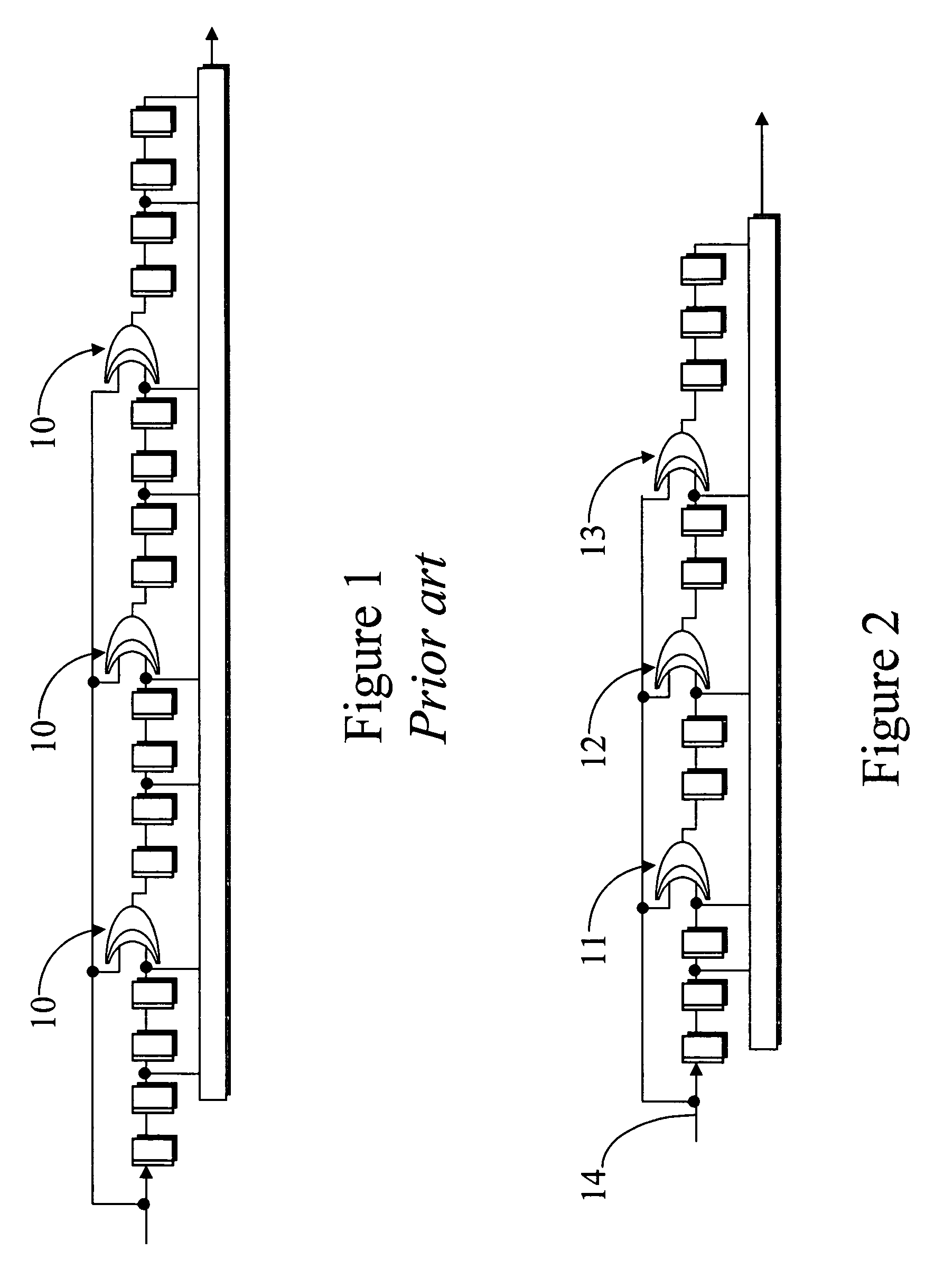
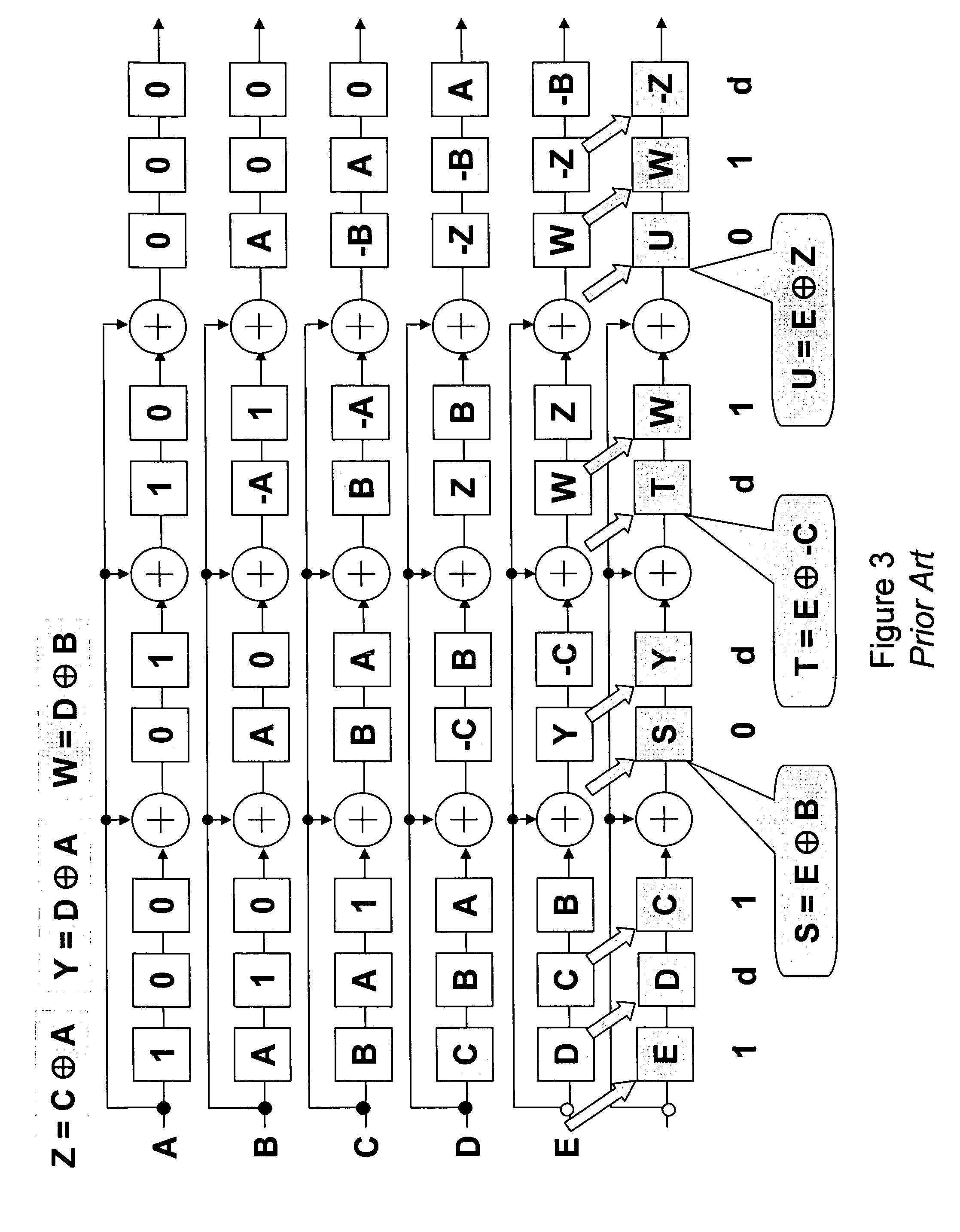
[0040]The prior art in FIG. 3, from U.S. patent application Ser. No. 10 / 750,949, depicts five shift cycles of forward symbolic simulation on a 10 bit long scan string broken into four segments by the addition of three exclusive-or gates, symbolically shown as a circle with a plus in it. This placement of exclusive-or gates is the same as shown in FIG. 2. The diagram in FIG. 3 shows the simulation states on the structure from an initial state on the top row through five consecutive shift cycles, to the bottom row. The simulation uses symbolic values A, B, C, D, and E applied on successive shifts, at the Scan_In port and shows the next state of the scan-chain after each shift cycle. On the 3rd shift (fourth row) a variable Z is introduced, on the 4th shift variables Y and W are introduced, and variables S, T and U are introduced on the fifth (and last) shift cycle. These variables are used as placeholders for the expressions they are equivalent to. This example demonstrates that setti...


PUM


Abstract

Addition of specific test logic may improve the level of test vector compression achieved from existing variable scan test logic. Methods for determining the compressed vectors' states, given the desired uncompressed vectors' values may be used, and techniques for selectively enabling test or other features on a chip by inserting the proper code or codes into the chip may further be used. Techniques may be used to incorporate and apply various types of reset operations to multiple strings of variable scan test logic, as may methods to minimize the test vector compression computation time.

Description

CROSS-REFERENCE TO RELATED APPLICATION[0001]This application claims the priority of now abandoned U.S. Provisional Patent Application No. 60 / 651,993, which is incorporated by reference herein.FIELD OF THE INVENTION[0002]The present invention is related to improvements in digital logic testing, particularly improvements to scan based digital logic testing, which uses check-sum or signature register logic and exclusive-or operations on serial shift string logic, and improvements to the corresponding software techniques to reduce test data volume and minimize test time.BACKGROUND AND SUMMARY OF THE INVENTION[0003]Prior co-pending U.S. patent application Ser. No. 10 / 351,276, filed on Jan. 24, 2003, published as U.S. Published Patent Application No. 20030229834 and U.S. patent application Ser. No. 10 / 750,949, filed on Jan. 5, 2004, published as U.S. Published Patent No. 20040148554, both by the inventors, and U.S. patent application Ser. No. 10 / 355,941, filed Jan. 31, 2003, published as ...

Claims


Application Information

Patent Timeline
Patent Type & Authority Patents(United States)
IPC IPC(8): G06F17/50
CPCG01R31/318552
Inventor COOKE, LAURENCE H.DERVISOGLU, BULENT I.
Owner INTELLECTUAL VENTURES I LLC
Why Eureka
Try Eureka