Muzzle-loading firearm

a firearm and muzzle-loading technology, applied in the field of muzzle-loading firearms, can solve the problems of high manufacturing cost, inconvenience, and a certain risk of mechanical problems

Inactive Publication Date: 2008-04-08
ARDESA
View PDF15 Cites 14 Cited by
  • Summary
  • Abstract
  • Description
  • Claims
  • Application Information

AI Technical Summary

Benefits of technology

[0012]The firing block is slidably connected to the frame part so that said firing block can slide rectilinearly (or at least substantially rectilinearly, and not in a pivoting manner as per the invention disclosed in my aforementioned U.S. patent application Ser. No. 11 / 051,282, the full disclosure of which is incorporated herein by reference), in a direction substantially perpendicular to a longitudinal axis of the barrel (for example, “downwards” and “upwards” when the firearm is in a position corresponding to the normal position of “use” of this kind of firearm), between a closed position in which the firing block covers the rear end of the breech plug with the firing pin channel aligned with said breech plug (and with the primer, when the primer has been attached to the rear end of the breech plug), and an open position in which the firing block does not cover the rear end of the breech plug. In this open position, the user can access the breech plug, for example, in order to insert a new primer and / or to remove a used primer. Thus, access to the breech plug is provided without any need for tilting the firing mechanism including hammer and trigger, etc. That is, the present invention provides for an extremely simple and reliable means for accessing the breech plug.
[0031]The barrel can be provided with a projection arranged for guiding the barrel in a guide groove in the frame part or in the barrel-protector, when mounting the barrel to the frame part or barrel-protector, respectively. Said projection can comprise a substantially prismatic body fixed (for example, welded) to the barrel. The projection can comprise at least two threaded holes for receiving respective screws (such as Allen screws) by means of which the barrel can be fastened to the frame part or barrel-protector. The barrel can further be provided with a further projection including a threaded hole for receiving a screw by means of which a barrel-protector can be (further) fastened to the barrel; this barrel-protector can serve to allow the user to support the firearm during use, without having the grip the barrel directly.

Problems solved by technology

A problem involved with this kind of firearms is the access to the rear end of the breech plug, which must be accessed in order to insert a primer, to replace a used primer or the withdraw a primer when unloading the firearm.
Traditionally, access to the breech plug has sometimes required the barrel to be removed, which, of course, may represent an inconvenience.
However, this pivoting mechanism involves a large number of movable parts and interrelated components, which may imply high manufacturing costs and a certain risk for mechanical problems.

Method used


Image

  • Muzzle-loading firearm
  • Muzzle-loading firearm
  • Muzzle-loading firearm

Examples


Embodiment Construction

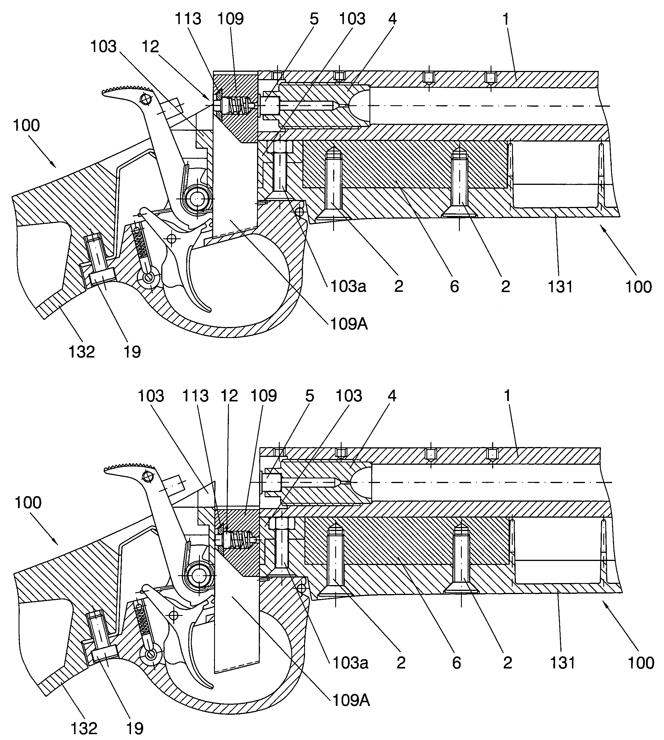
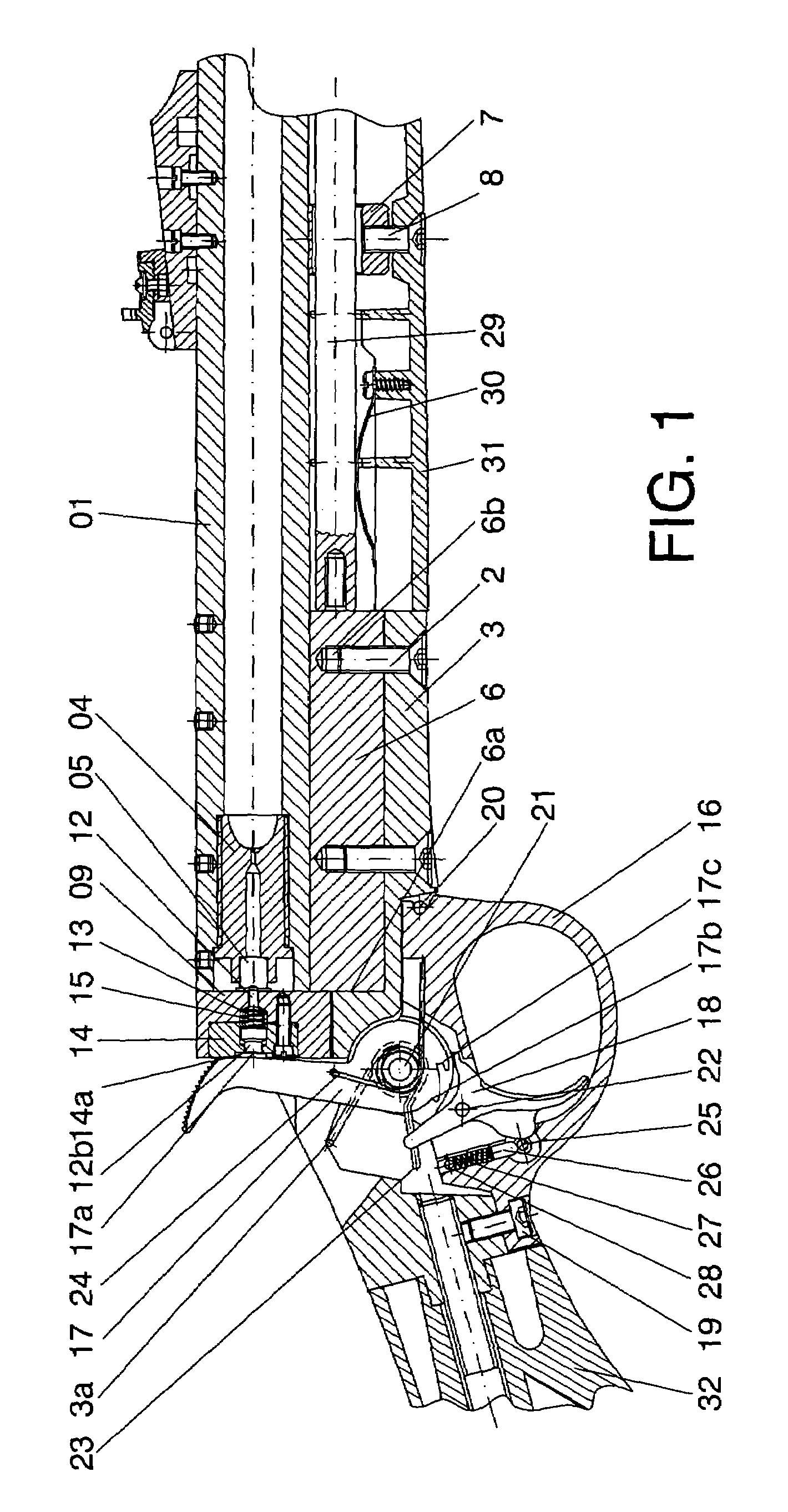
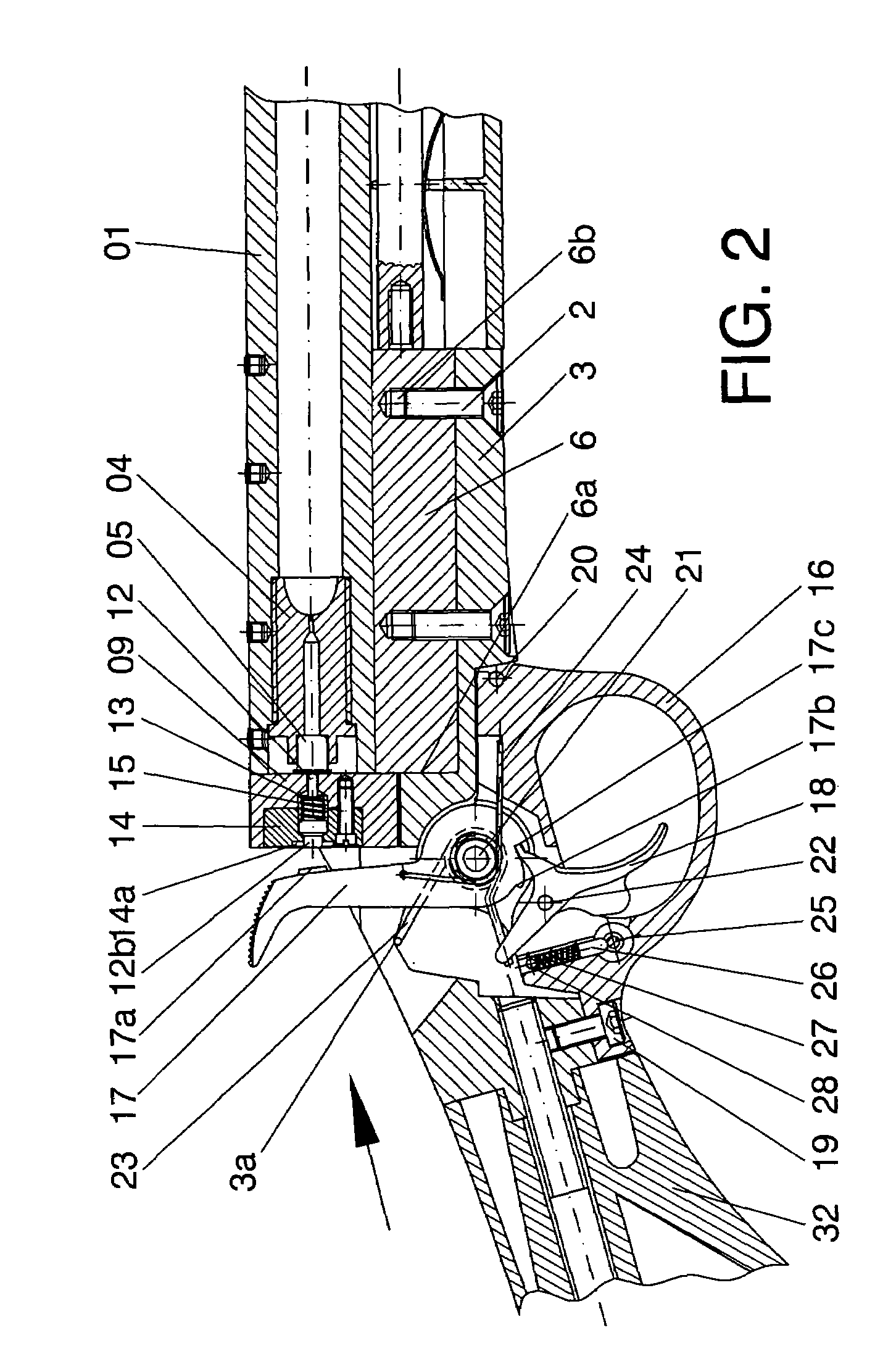
[0049]FIG. 9 shows an exploded view of the firearm in accordance with one possible embodiment of the present invention (but featuring a firing block, barrel-protector and frame part as disclosed in U.S. patent application Ser. No. 11 / 051,282; however, the rest of the illustrated firearm are directly applicable to the present invention, whereby only the firing block and, optionally, the frame part and the barrel-protector and butt arrangement need to be adapted as shown in FIGS. 10-13B). The barrel 1 has a front or muzzle end and a rear end arranged to be received by a frame part 3 (or directly by a barrel-protector 131 forming part of a single piece 100 made of plastic, such as suggested in FIGS. 10, 11 and 14). A breech plug 4 is arranged to be screwed into the rear end of the barrel. The breech plug has a rear end arranged to receive a primer 5 (cf., for example, FIG. 1) and a front end, against which the powder charge is applied when the firearm is loaded through the muzzle end o...


PUM


Abstract

A muzzle-loading firearm has a barrel, a frame part, a breech plug, and a firing block arranged adjacent to the rear end of the breech plug, the firing block being slidably connected to the frame part so that said firing block can slide rectilinearly, in a direction substantially perpendicular to a longitudinal axis of the barrel, between a closed position in which the firing block covers the rear end of the breech plug, and an open position in which the firing block does not cover the rear end of the breech plug.

Description

FIELD OF THE INVENTION[0001]The invention relates generally to muzzle-loading firearms.BACKGROUND OF THE INVENTION[0002]Because of their classical character, muzzle-loading firearms are popular among sport enthusiasts. For shooting with this kind of firearms, normally, a primer is applied to a rear end of a breech plug inserted in one end of the barrel (the breech end of the barrel), and this primer is used to ignite a powder charge situated inside the barrel, at a front end of said breech plug, whereby front end means the end closest to the muzzle and the rear end the end furthest away from the muzzle.[0003]A problem involved with this kind of firearms is the access to the rear end of the breech plug, which must be accessed in order to insert a primer, to replace a used primer or the withdraw a primer when unloading the firearm. Further, access to the breech plug should preferably be easy in order to allow for easy cleaning of the corresponding parts of the firearm.[0004]Traditiona...

Claims


Application Information

Patent Timeline
Patent Type & Authority Patents(United States)
IPC IPC(8): F41C7/00F41A3/10
CPCF41C9/08
Inventor CALVETE ZUMALDE, ANGEL
Owner ARDESA
Why Eureka
Try Eureka