Method for adjusting reel-to-bedknife clearance

a cutting reel and clearance technology, applied in the field of mower cutting reel units, can solve the problems of time-consuming re-tasking of cutting reel units, difficult to achieve proper mower adjustments through manual adjustment methods, and high capital costs and maintenance costs, and achieves speed and consistency advantages, automatic adjustment, and speed and consistency advantages

Active Publication Date: 2008-04-08
DEERE & CO
View PDF20 Cites 5 Cited by
  • Summary
  • Abstract
  • Description
  • Claims
  • Application Information

AI Technical Summary

Benefits of technology

[0024]Alternatively to operator initiation, the cutting reel adjustments can also be initiated by a controller or control units that is / are responsive to a sensor such as a height of grass sensor, or by a location sensor and / or sender on the cutting unit or cutting machine that communicates with an external ground-based system or a global positioning system (GPS). These systems, responsive to external conditions, along with the onboard control systems as described herein facilitate implementation of the control system in either a manned cutting machine or an autonomous cutting machine.
[0033]The disclosed invention provides advantages in that the apparatus and method allow for rapid and automatic adjustment of the reel-to-bedknife gap without operator intervention following operator initiation of the adjustment. The reel can be adjusted in seconds. The method has speed and consistency advantages over manual adjustment, and does not require detection of poor cut quality or excess surface wear in order to perform the automatic adjustment.
[0034]The disclosed invention provides advantages in that the apparatus and method allow for rapid and automatic adjustment of the height-of-cut of a reel of a cutting reel unit without operator intervention following operator initiation of the adjustment. The reel can be adjusted in seconds. The method has speed and consistency advantages over manual adjustment, and does not require detection of poor cut quality in order to perform the automatic adjustment.
[0035]By making these adjustments automatically, the reel adjustment process may be accomplished more consistently without the presence of a skilled mechanic. The automated adjustment also provides the capability for the support of autonomous equipment.
[0036]The control system allows a cutting reel unit to be rapidly re-tasked to cut different grass heights for different areas of a golf course. The system allows a single cutting reel unit to be readily usable for multiple golf course areas.
[0037]To provide a more accurate and precise final adjustment of the reel-to-bedknife gap for a reel cutting unit, once contact is detected between the reel and bedknife, the adjustment actuators may reverse direction and be energized in a direction that would increase the gap, while the control system continues to monitor the detectors. Contact between the reel and bedknife will continue to be detected until true motion occurs such that a gap is formed between the reel and bedknife. The location where contact between the reel and bedknife is no longer detected is the “zero-gap point.” Until reaching this position, the control system does not monitor the incremental position sensor. After true motion has begun, the control system monitors the incremental position sensor data and may command the actuators to increase the gap to a specific final gap position.

Problems solved by technology

However, re-tasking a cutting reel unit is time-consuming.
Multiple cutting units or machines can result in higher capital costs and maintenance costs.
The present inventors have recognized that proper mower adjustments are often hard to achieve through manual adjustment methods.
The present inventors have recognized that the reel-to-bedknife adjustment is one such adjustment that needs to be adjusted accurately and precisely, but is often hard to achieve on individual mowing reels.
The present inventors have recognized that the reel height-of-cut adjustment is another such adjustment that needs to be adjusted accurately and precisely, but is also difficult to adjust on individual mowing reels.

Method used


Image

  • Method for adjusting reel-to-bedknife clearance
  • Method for adjusting reel-to-bedknife clearance
  • Method for adjusting reel-to-bedknife clearance

Examples


Embodiment Construction

[0056]While this invention is susceptible of embodiment in many different forms, there are shown in the drawings, and will be described herein in detail, specific embodiments thereof with the understanding that the present disclosure is to be considered as an exemplification of the principles of the invention and is not intended to limit the invention to the specific embodiments illustrated.

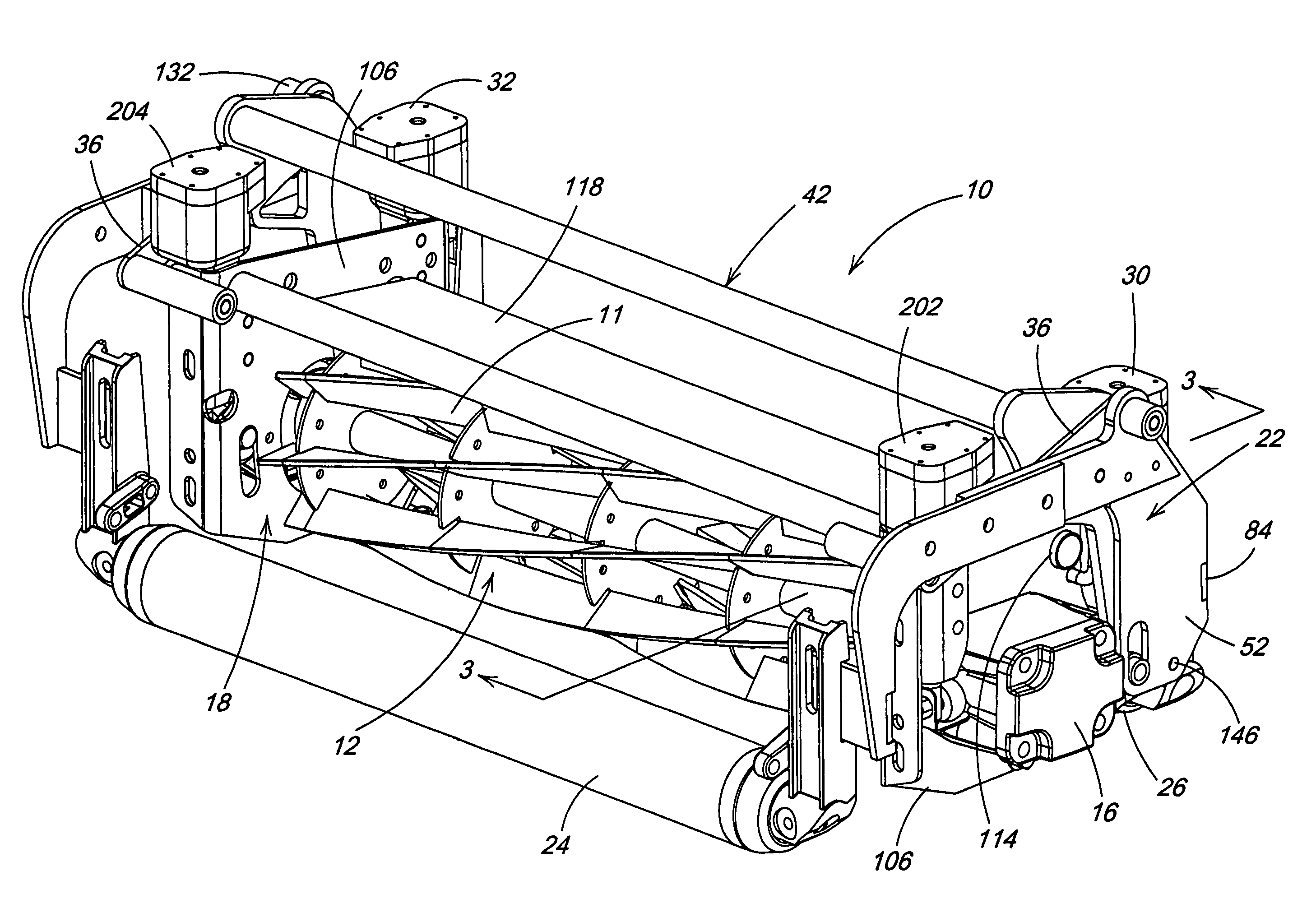
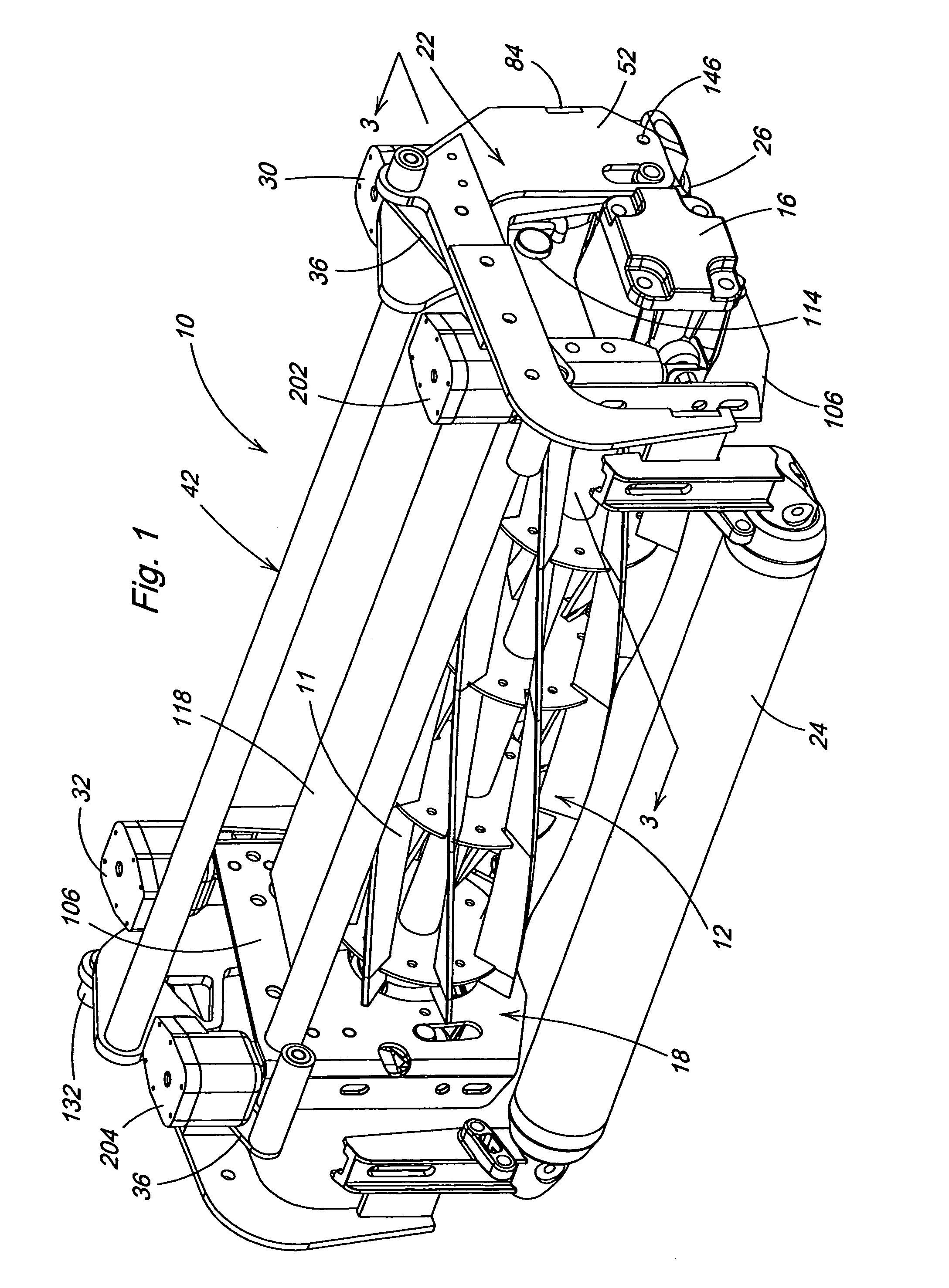
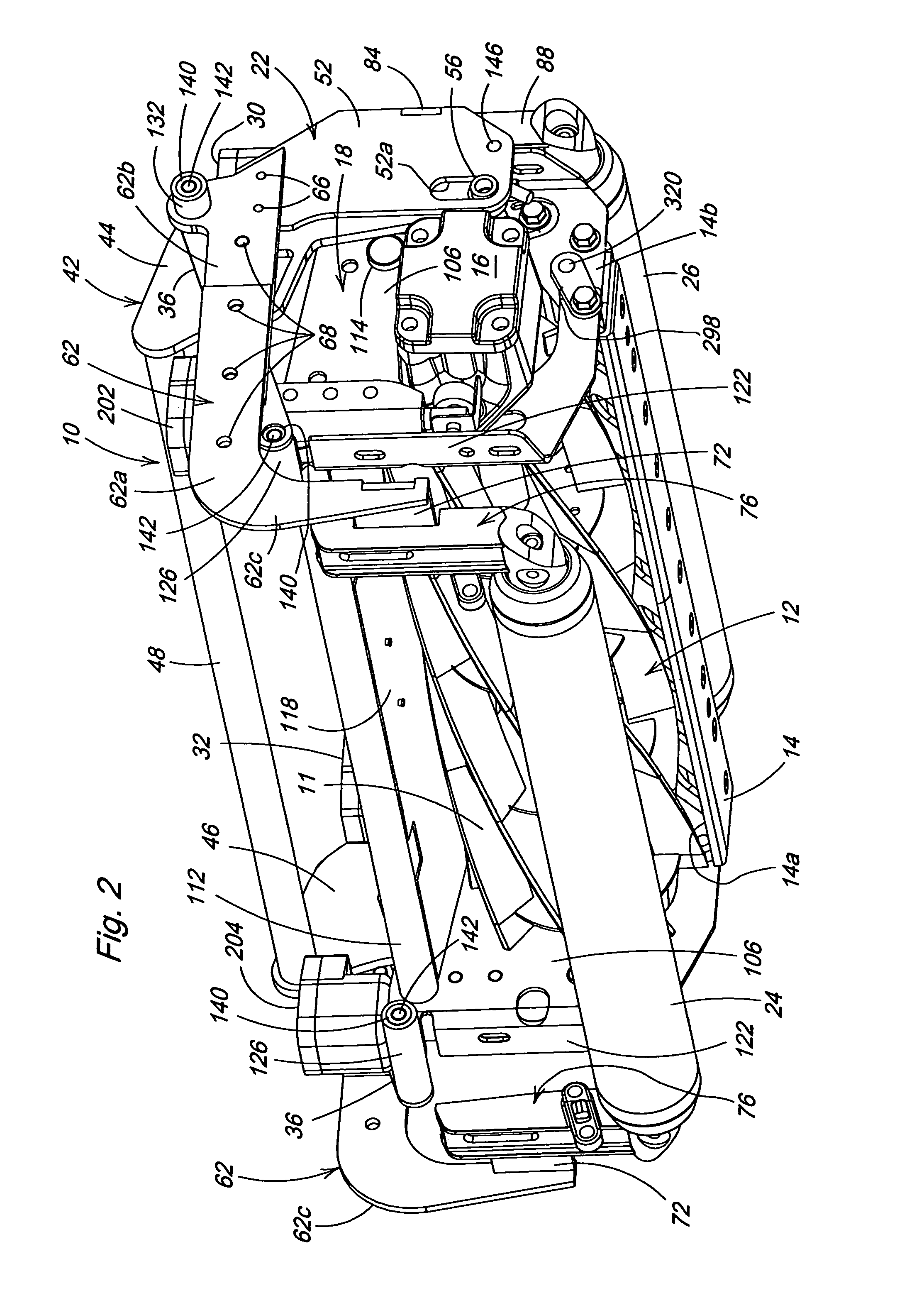
[0057]FIGS. 1 and 2 illustrate a mower cutting reel unit 10 according to the present invention. The mower cutting reel unit 10 is adapted to be pulled alone or within a group of like units by a vehicle such as described in U.S. Pat. No. 5,343,680; 5,412,931 or 5,459,984, herein incorporated by reference. A plurality of blades 11 are coupled together to form a generally cylindrical reel 12 which rotates about a transverse axis in close proximity to an edge 14a of a bedknife 14 (FIG. 2) for cutting vegetation, such as grass, with a scissoring action. A motor 16, carried at one side of a frame 18 th...


PUM


Abstract

A control system for a cutting reel unit includes a height-of-cut adjusting system and a reel-to-bedknife clearance adjusting system. The height-of-cut adjusting system includes a first frame; a second frame; a cutting reel supported by the second frame; a bedknife arranged adjacent to the cutting reel and supported by the second frame; at least one support element arranged to translate along the ground and arranged to support the first frame; and at least one first actuator connected between the first frame and the second frame and arranged to adjust the relative elevation of the second frame with respect to the first frame. The reel-to-bedknife clearance adjusting system includes at least one second actuator operatively connected between the reel and the second frame and a sound detector. Once contact is detected between the reel and bedknife, the adjustment actuators may reverse direction and be energized in a direction that would increase the gap. Contact between the reel and bedknife will continue to be detected until true motion occurs such that a gap is formed between the reel and bedknife. The location where contact between the reel and bedknife is no longer detected is the “zero-gap point.” After true motion has begun, the control system monitors the incremental position sensor data and may command the actuators to increase the gap to a specific final gap position.

Description

TECHNICAL FIELD OF THE INVENTION[0001]The invention relates to cutting reel units for mowers, and particularly systems-based mechanisms and methods for adjusting cutting reel units.BACKGROUND OF THE INVENTION[0002]Conventional mowing machines have an attached cutting reel unit or multiple units. Such machines typically move the cutting reel unit across the ground adjacent to the machine. Grass beneath the cutting reel unit is mowed as the machine travels forward. Conventional reel mower vehicles can include a plurality of arm members that extend from the vehicle, each arm having a cutting reel unit attached to its outer end portion.[0003]The cutting reel units typically include front and rear skids or rollers that support or carry the cutting reel unit across the surface of the ground during mowing operation. Such vehicles and cutting reel units are disclosed for example in U.S. Pat. Nos. 5,343,680; 5,412,931 and 5,459,984.[0004]Conventional cutting reel units provide a plurality of...

Claims


Application Information

Patent Timeline
Patent Type & Authority Patents(United States)
IPC IPC(8): A01D34/53
CPCA01D34/62
Inventor SILBERNAGEL, CARL STEVEN
Owner DEERE & CO
Why Eureka
Try Eureka