Flexible and protective mailbox mount

a mailbox mount, flexible technology, applied in the field of mailbox mounts, can solve the problems of mailboxes not being many areas have been plagued with considerable damage to mailboxes, and mailboxes are not able to resist damage, so as to prevent permanent damage to mailboxes

a mailbox mount, flexible technology, applied in the field of mailbox mounts, can solve the problems of mailboxes not being many areas have been plagued with considerable damage to mailboxes, and mailboxes are not able to resist damage, so as to prevent permanent damage to mailboxes

US7353985B1Inactive Publication Date: 2008-04-08WEATHERHOLT II MICHAEL J

Image

  • Flexible and protective mailbox mount
  • Flexible and protective mailbox mount
  • Flexible and protective mailbox mount

Examples


Embodiment Construction

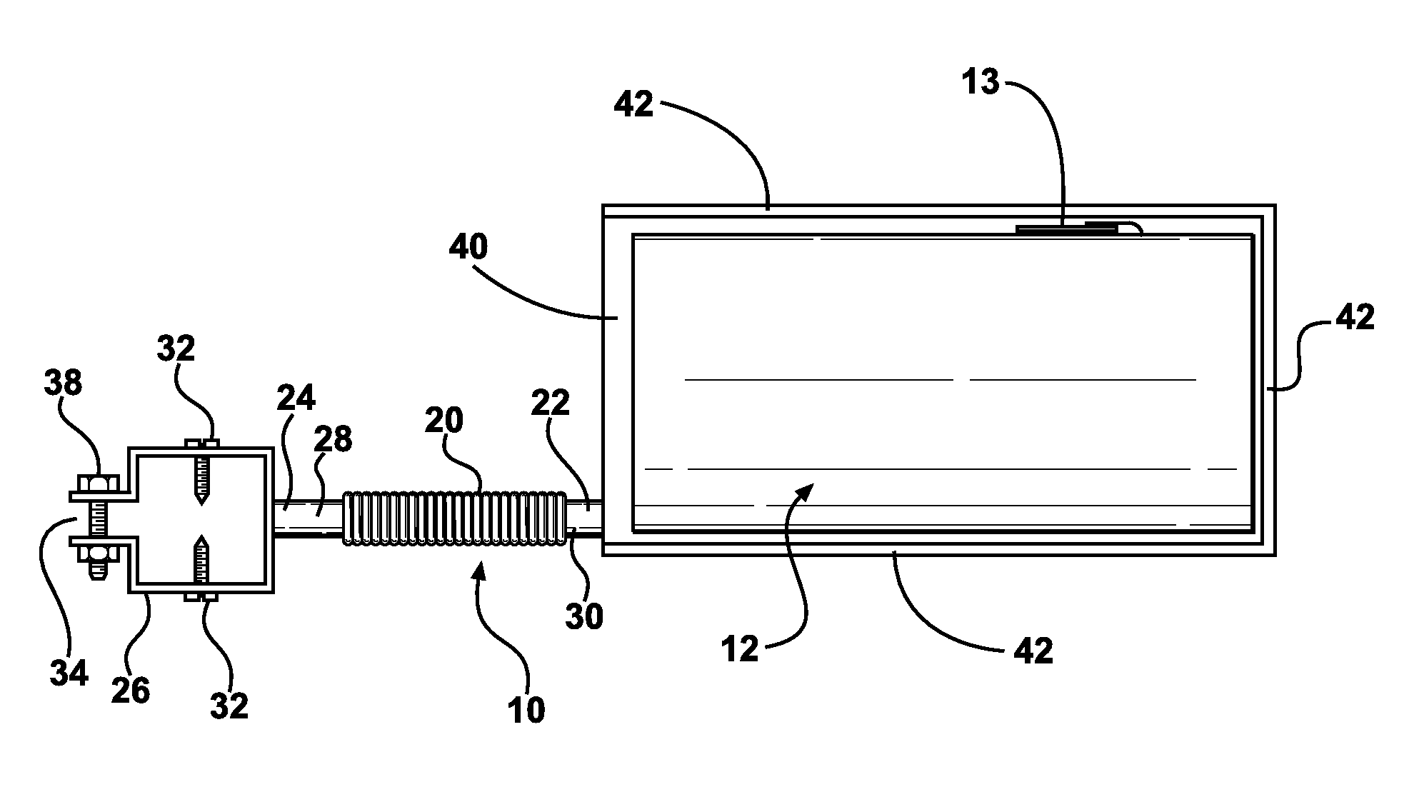
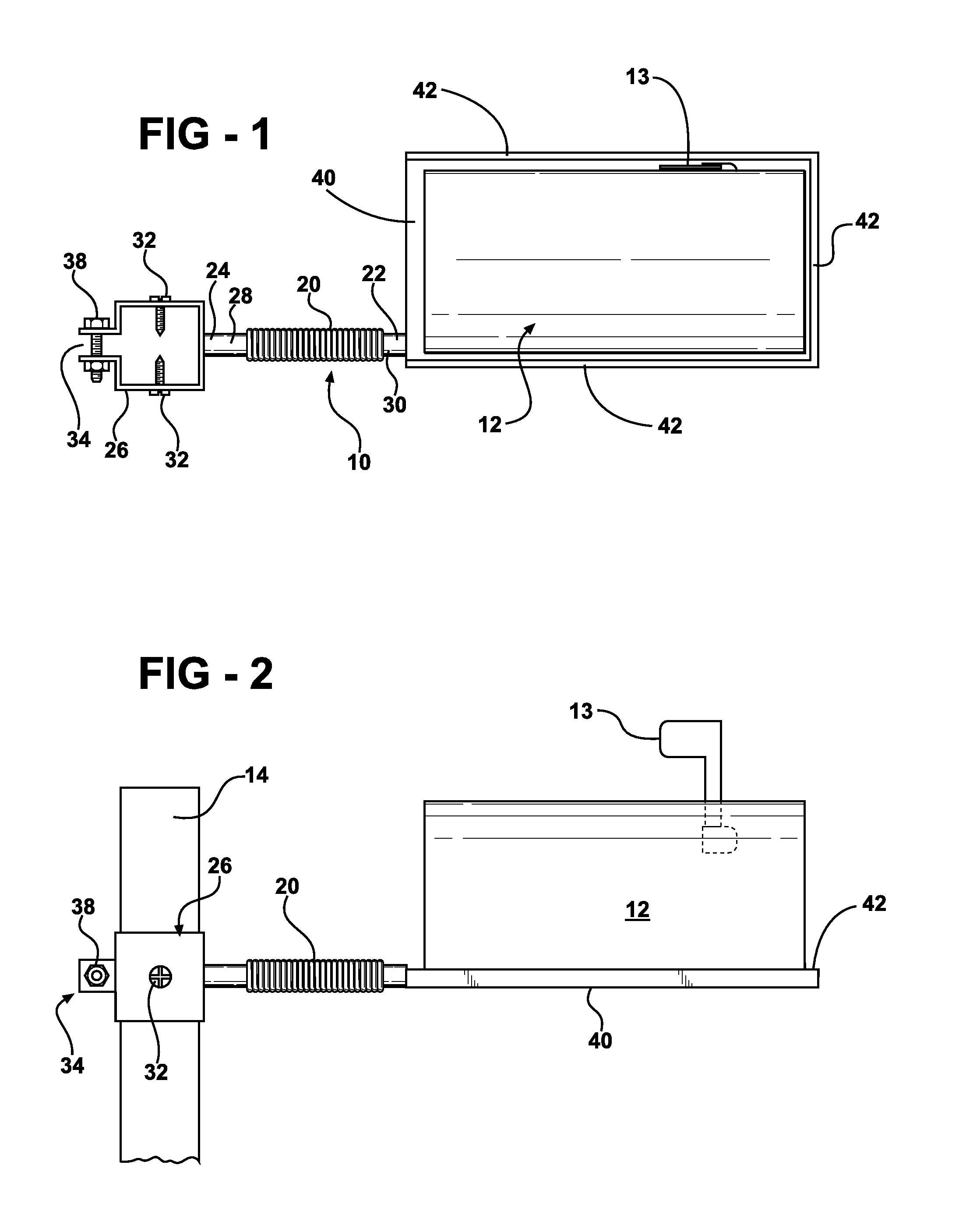
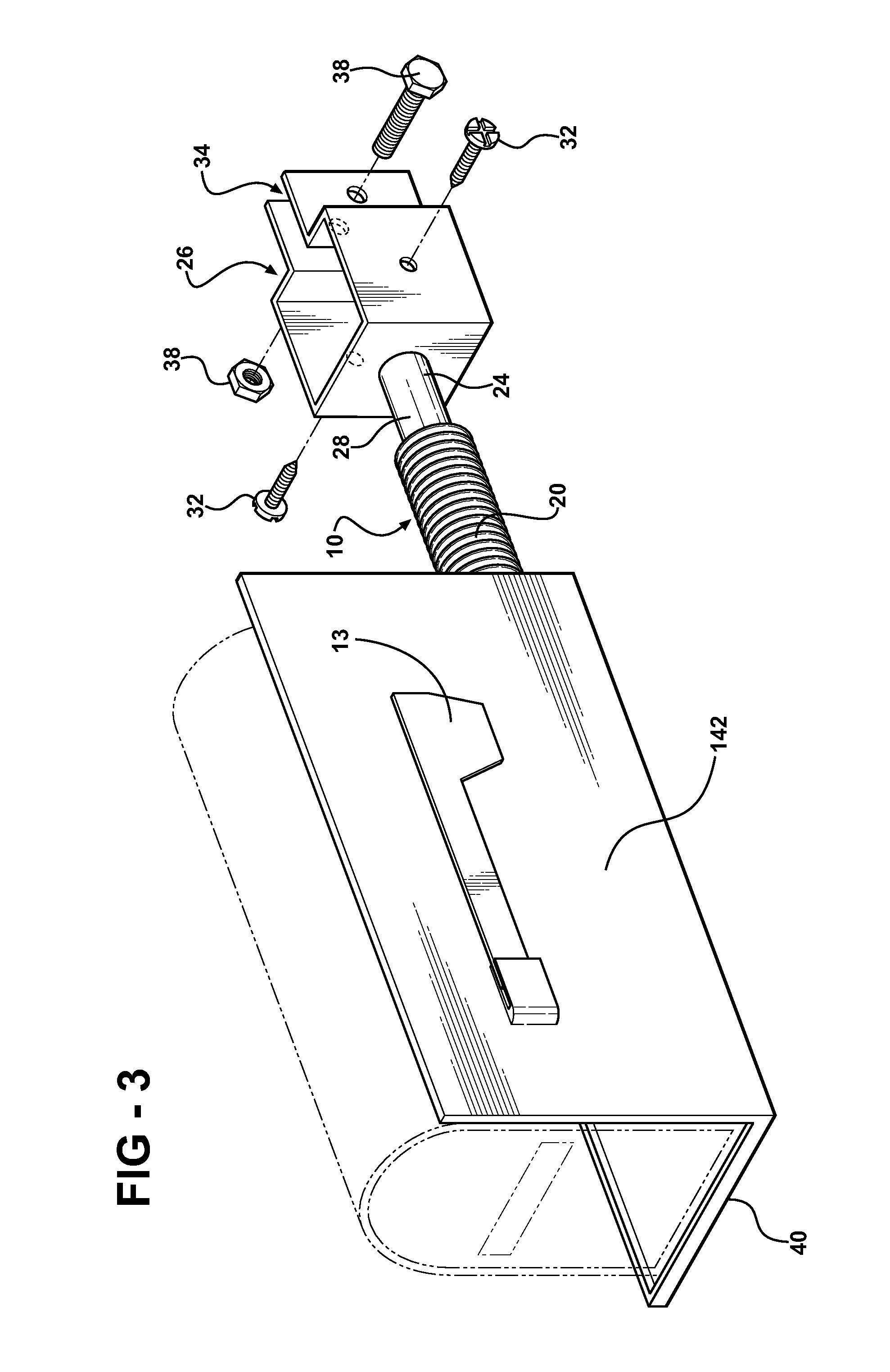
[0013]Other objects, features and advantages of the invention will become apparent from a consideration of the following detailed description and the accompanying drawings. Referring to the figures, it can be understood that the present invention is embodied in a support system 10 for attaching a mailbox 12 to a support, such as a post 14 in a manner which permits movement of the mailbox with respect to the support without permanently damaging the mailbox or its support system.

[0014]Support system 10 includes a heavy duty spring 20 having one end 22 fixed to the mailbox and a second end 24 fixed to a bracket 26 by elements 28 and 30. Spring 20 can be any suitable heavy duty spring.

[0015]Bracket 26 includes fasteners, such as screws 32, for attaching the bracket to support 14, and a tightening ear unit 34 which includes a fastening bolt 38. If the mailbox is contacted by a vehicle, such as a snowplow, the mailbox will simply give and swing back and forth on the post due to the resili...


PUM


Abstract

A mailbox mount which includes a heavy-duty spring connecting the mailbox to post via a mounting element. The spring allows the mailbox to return to its initial position after being contacted by another item, such as a snowplow or the like to prevent permanent damage to the mailbox. The mailbox mount also includes a mailbox mounting plate with a protective lip or shield on at least the delivery side of the mailbox.

Description

RELATED APPLICATION[0001]This application is a non-provisional of, and claims priority to, co-pending provisional application No. 60 / 793,235 by the same inventor, filed Apr. 20, 2006, which is hereby incorporated in its entirety by reference.TECHNICAL FIELD OF THE INVENTION[0002]The present invention relates to the general art of mailboxes, and to the particular field of mounts for mailboxes.BACKGROUND OF THE INVENTION[0003]In rural and many suburban areas, mail is delivered to residences and places of business by a delivery person placing the mail into a mailbox positioned at the side of a street or road. Such a mailbox typically includes a box-like housing having a door located on the front of the housing, and the housing is mounted to a post which is secured in the ground. A flag is usually pivotally connected to the mailbox housing, movable between a lowered position and a raised position. The flag can be moved to the raised position to indicate either that a delivery has been m...

Claims


Application Information

Patent Timeline
08 Apr 2008
Publication
US7353985B1
IPC
A47G29/12
CPC
A47G29/1216
Inventors
WEATHERHOLT, II, MICHAEL J.