Thrust bearing

a technology of thrust bearings and bearings, which is applied in the direction of bearings, shafts and bearings, rotary bearings, etc., can solve the problems of thrust bearings that are not suitable for us

Inactive Publication Date: 2008-04-08
FEDERAL MOGUL WORLD WIDE LLC
View PDF19 Cites 31 Cited by
  • Summary
  • Abstract
  • Description
  • Claims
  • Application Information

AI Technical Summary

Benefits of technology

[0008]When installed in an engine to journal a crankshaft with thick and thin flanges oppositely arranged, thrust forces exerted by the crankshaft in one axial direction confront the thick flange of one of the bearings causing it to seat firmly in the block. Likewise, thrust forces exerted by the crankshaft in the opposite direction confront the thick flange of the other bearing causing it also to seat firmly in the block. Once seated, it is highly desirable to keep the bearings seated and shield them against any forces, which would cause them to unseat. The present invention provides such protection.
[0009]This invention has the advantage of recessing the outer axial faces of the thin flanges axially inwardly of the faces of the thick flanges and by doing so, the crank shaft confronts only the thick flanges is prevented from contacting the thin flanges. As such, this construction and arrangement of the bearings isolates the bearings from any axial “unseating” forces that may otherwise be imparted by the crank shaft to the thin flanges and cause the associated bearings to shift away from this initial fully seated condition. Preventing the condition of repeated seating and unseating further isolates the bearings from bending forces that, over time, could lead to weakening or failure of the bearings.
[0010]The invention has the further advantage of enabling companion bearings to be identically constructed for manufacturing simplicity and cost savings.

Problems solved by technology

However, this reverse force also has the effect of unseating the forward-most set of thrust flanges.
While the unseated thrust flanges will be re-seated the next time the axial thrust forces imported by the crankshaft change, this constant seating and unseating has the detrimental effect of repeatedly bending and thus stressing the thrust bearing of the base of the thrust flanges, which can lead to premature failure of the thrust bearing.
Additionally, the repeated seating and unseating can cause the thrust bearing to become misaligned which can also lead to unwanted stress and failure of the thrust bearings.

Method used


Image

  • Thrust bearing
  • Thrust bearing
  • Thrust bearing

Examples


Embodiment Construction

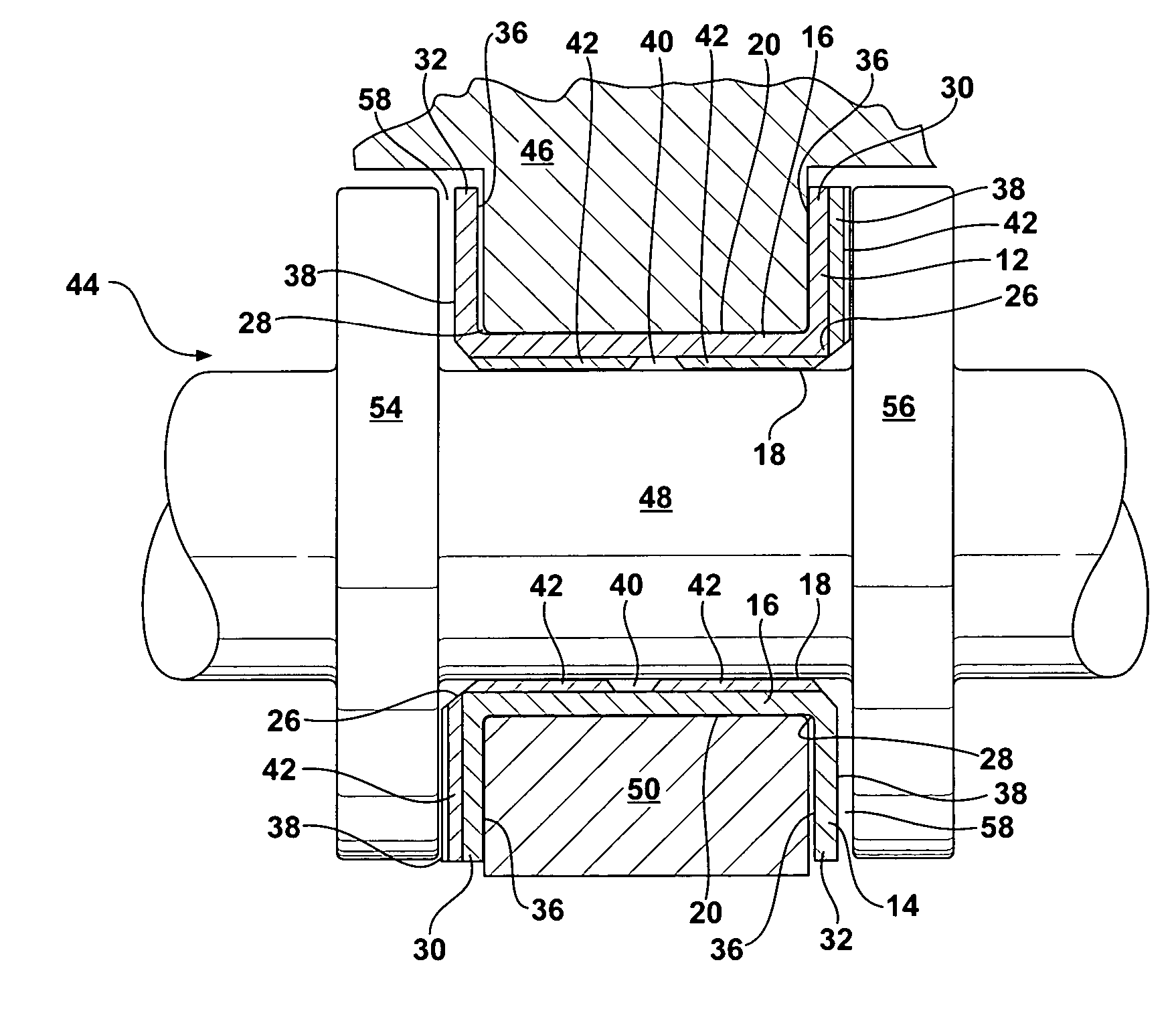
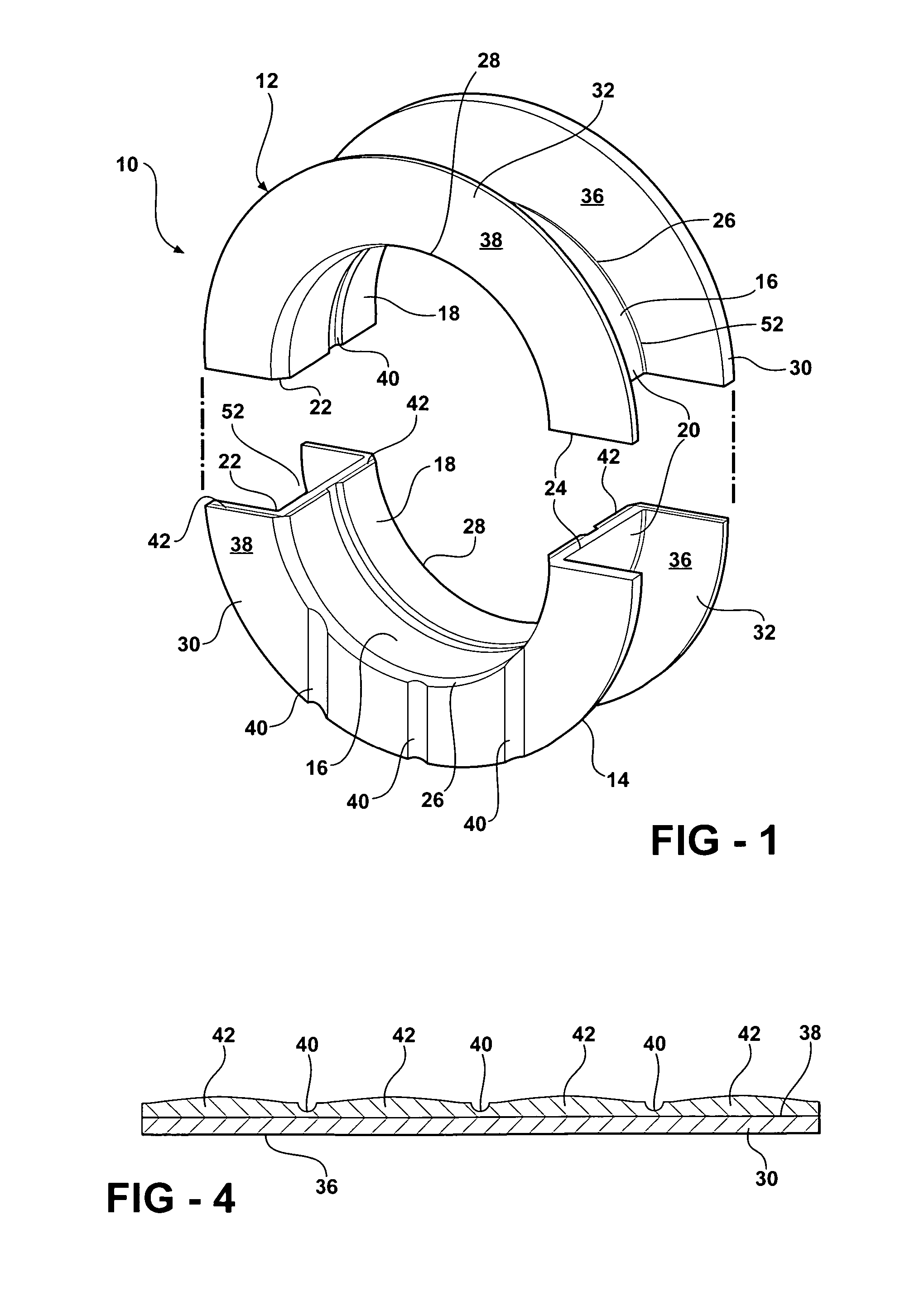
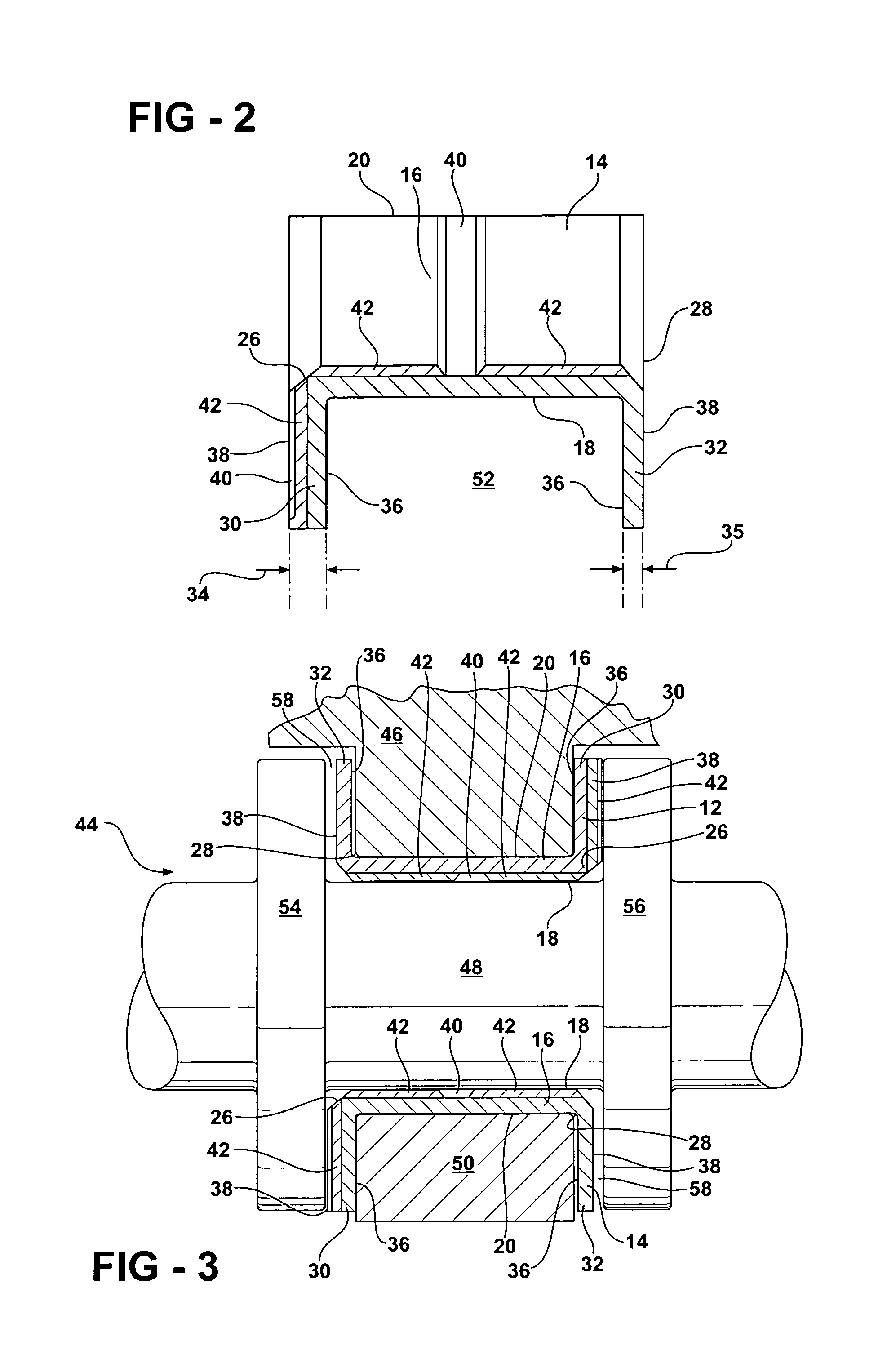
[0016]A thrust bearing assembly is shown generally at 10 in FIG. 1. The thrust bearing assembly 10 includes an upper thrust bearing 12 and a lower thrust bearing 14. A cross-sectional view of the lower thrust bearing 14 is illustrated in FIG. 2. It is to be appreciated that the upper and lower thrust bearings 12, 14 are substantially identical, as will be described below.

[0017]Both of the upper and lower thrust bearings 12, 14 include an arcuate bearing shell 16 with a concave inner surface 18 and a convex outer surface 20. The bearing shell 16 extends between first and second ends 22, 24, as shown in FIG. 1, and extends axially between opposite edges 26, 28.

[0018]A pair of flanges, a thick flange 30 and a thin flange 32, extend radially outwardly of the bearing shell 16 from the opposite edges 26, 28 thereof. The flanges 30, 32 are formed as one part, or piece, with the bearing shell 16 from a same material. The material is formed and cut into desired lengths. Then the material is ...


PUM

PropertyMeasurementUnit
thrustaaaaaaaaaa
clearance distanceaaaaaaaaaa
thicknessaaaaaaaaaa

Abstract

A thrust bearing assembly includes an upper thrust bearing and a lower thrust bearing for use in an engine assembly of a vehicle and which, are preferably, identically configured. The upper and lower thrust bearings each include an arcuate bearing shell with a concave inner surface and a convex outer surface and each may be formed with a pair of axially spaced flanges extending radially outwardly of the bearing shells. The flanges may be formed as one piece with the bearing shell and the thickness of one of the flanges is greater than that of the other of the flanges. The thicker flanges are load bearing and preferably contoured, whereas the thinner flanges are not. The bearings are installed with the thick flange of each bearing matched radially opposite the thin flange of the companion bearing to minimize fatigue and failure normally attributed to repeated seating and unseating of the bearing assemblies having flanges of equal thickness caused by changing bending loads imparted by a shaft.

Description

BACKGROUND OF THE INVENTION[0001]1. Field of the Invention[0002]The subject invention relates to a thrust bearing assembly as part of an engine assembly for use in a vehicle and a method of aligning a thrust bearing in the engine assembly.[0003]2. Description of the Related Art[0004]Crankshafts are journaled in engine blocks by a series of axially spaced engine bearings. Each engine bearing includes-an upper bearing half seated in an arcuate recess of the block and an accompanying lower bearing half clamped tightly against the upper bearing half by a supportive bearing cap bolted to the engine block. At least one of the engine bearings in the set is designed to absorb axial thrust forces imported by the crankshaft during operation. The so-called thrust bearing differs from the other engine bearing in that it has two axially spaced thrust flanges that project radially outwardly. The thrust bearing presents opposite axially outwardly directed thrust faces which are seated on their bac...

Claims


Application Information

Patent Timeline
Patent Type & Authority Patents(United States)
IPC IPC(8): F16C9/02
CPCF16C9/00F16C17/10F16C17/047F16C33/1075Y10T29/497Y10T29/49645Y10T29/49696F16C17/00F16C33/00F16C33/06F16C35/00
Inventor WELCH, SEAN M.THOMPSON, RONALD J.
Owner FEDERAL MOGUL WORLD WIDE LLC
Why Eureka
Try Eureka