Optical touch screen arrangement

a touch screen and optical technology, applied in the field of touch screens, can solve the problems of reducing the brightness and contrast of the display, consuming too much power for some applications, and using flexible membrane technology that has not been proven to be adequately durable for demanding commercial applications

Active Publication Date: 2008-04-08
SYMBOL TECH LLC
View PDF2 Cites 55 Cited by
  • Summary
  • Abstract
  • Description
  • Claims
  • Application Information

AI Technical Summary

Benefits of technology

[0007]Accordingly, it is a general object of this invention to provide a durable optical touch screen arrangement which requires no delicate, flexible membranes to wear out or become damaged.
[0008]More particularly, it is an object of the present invention to provide an optical touch screen arrangement which does not reduce screen brightness or contrast.
[0009]Still another object of the present invention is to provide an optical touch screen arrangement which is easily adapted to a variety of screen sizes.
[0010]It is yet another object of the present invention to provide an optical touch screen arrangement which has minimal power consumption.FEATURES OF THE INVENTION
[0013]Hence, there are no flexible membranes to wear out or become damaged, as in the prior art. Screen brightness or contrast is not affected. Power consumption is low. The dual imager mounting is easily adapted to a variety of screen sizes.
[0016]Although ambient light can be used, more reliable image capture and results are obtained if an illumination system is built into the arrangement. The illumination system may illuminate a frame surrounding the screen, especially with infrared light to which the imagers are sensitive, or illumination light emitting diodes can be mounted near each imager. Another variation is to place a reflector on a tip of a pen, or to place a light emitting diode at the pen tip, for better results.

Problems solved by technology

These use flexible membrane technology that has not proven to be adequately durable for demanding commercial applications.
In addition, the membranes are positioned over the display, reducing the brightness and contrast of the display.
While this kind of technology works well for sensing finger touches in applications such as automated teller machines, where high resolution of the location of the touch is not necessary, signature capture, while possible, requires such a dense population of sensors and LEDs as to become too expensive and to use too much power for some applications.

Method used


Image

  • Optical touch screen arrangement
  • Optical touch screen arrangement
  • Optical touch screen arrangement

Examples


Embodiment Construction

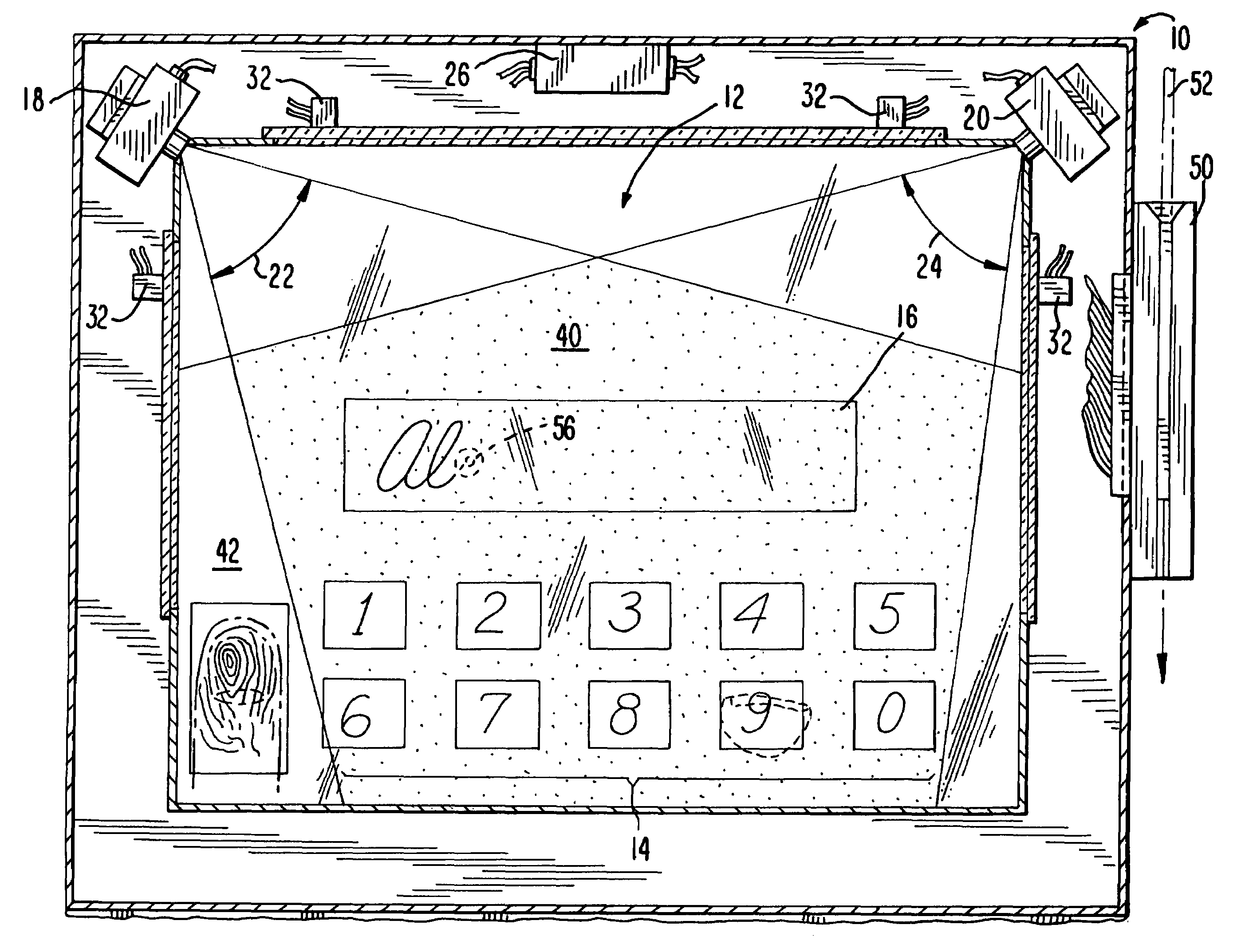
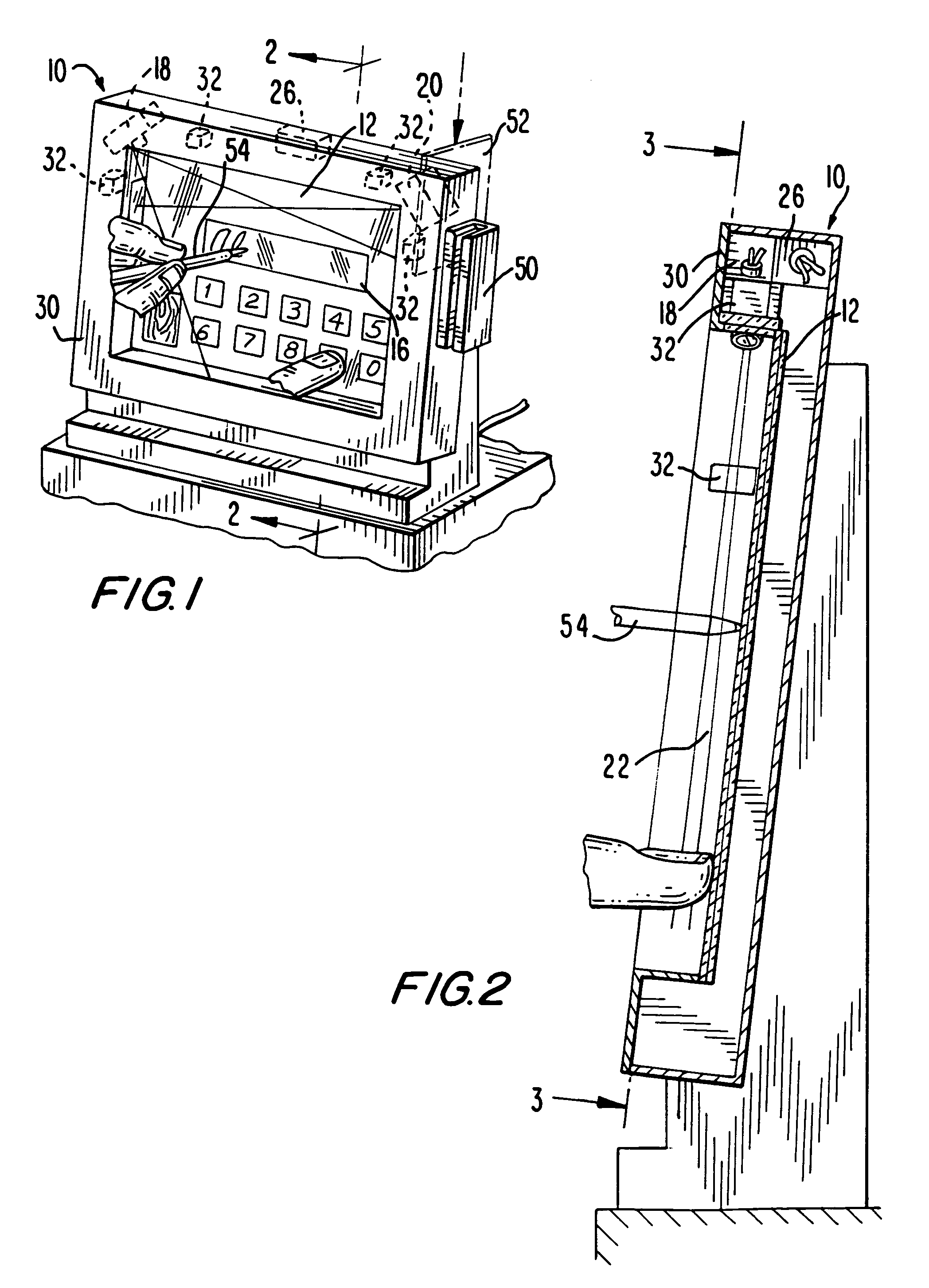
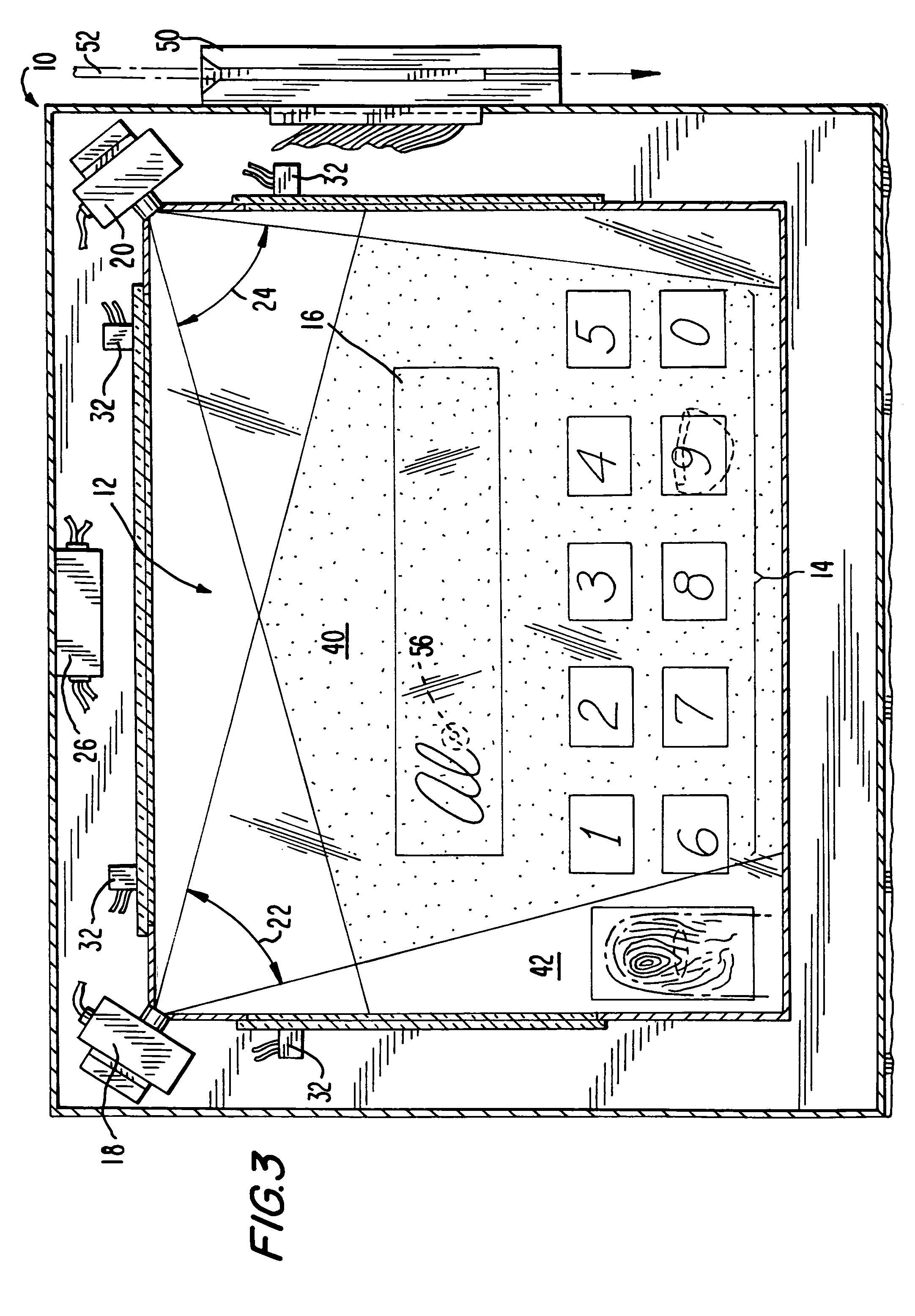
[0021]Reference numeral 10 depicts a typical embodiment that would be used as a payment terminal, such as would be used to capture a signature when paying with a credit card 50 swiped through a card reader 52 at a department store. In this application, a screen 12 having a size typically around 4 inches by 5 inches is used. The screen 12 will display a numeric keypad 14 (buttons 0-9) when a consumer is to enter a personal identification number when paying with the card 50, or it can display a box 16 in which the consumer is required to place his / her signature when paying.

[0022]In a preferred embodiment, two single line imaging cameras 18, 20 are used to locate the point where a user, or a pen 54, touches the screen 12, or to follow the location of a pen tip 56 as the user writes a signature. The cameras are located at two corners of the screen, such as at the upper left corner and at the upper right corner, but not at diagonally opposite corners (unless more than two cameras are use...


PUM


Abstract

An optical touch screen arrangement includes two optical cameras arranged so that their planar fields of view intersect each other in a touch area situated adjacent a display screen operative for displaying visual prompts to solicit action from a user. The user's finger, or a pen, entering the touch area is detected, as is the user's signature.

Description

BACKGROUND OF THE INVENTION[0001]1. Field of the Invention[0002]The present invention generally relates to touch screens and, more particularly, to optical touch screens having signature capture capability.[0003]2. Description of the Related Art[0004]Touch screens and signature capture devices are well known on personal digital assistants, payment terminals, and portable computers designed for various markets. These touch / signature capture screens have made use of various technologies. Each of these, however, has some disadvantages.[0005]The most common type of technology is found on hand-held personal digital assistants. These use flexible membrane technology that has not proven to be adequately durable for demanding commercial applications. In addition, the membranes are positioned over the display, reducing the brightness and contrast of the display.[0006]Other technologies include capacitive sensors mounted on the screen, as well as infrared (IR) light emitting diodes (LEDs) pos...

Claims


Application Information

Patent Timeline
Patent Type & Authority Patents(United States)
IPC IPC(8): G09G5/00
CPCG06F3/0428
Inventor BARKAN, EDWARD
Owner SYMBOL TECH LLC
Why Eureka
Try Eureka