Methods of monitoring downhole conditions

a technology of downhole conditions and monitoring methods, applied in the field of monitoring downhole conditions, can solve the problems of inability to provide a permanent monitoring system and the inability to provide noise log tools,

Active Publication Date: 2008-04-15
WELLDYNAMICS INC
View PDF37 Cites 58 Cited by
  • Summary
  • Abstract
  • Description
  • Claims
  • Application Information

AI Technical Summary

Problems solved by technology

Such conventional noise log technology, however, provides only a “one-shot” survey, in that it only provides information when the noise log tool is actually run into the well and therefore cannot provide a permanent monitoring system since the noise log tool cannot reside permanently within the well.
Furthermore, the measurements provided by the noise log tool may be affected by the very presence of the noise tool in the flow.

Method used


Image

  • Methods of monitoring downhole conditions
  • Methods of monitoring downhole conditions
  • Methods of monitoring downhole conditions

Examples


embodiment 1

Determination and Identification of Flow Regime from an Acoustic Profile

[0048]One or more embodiments in accordance with the first aspect of the present invention will now be described.

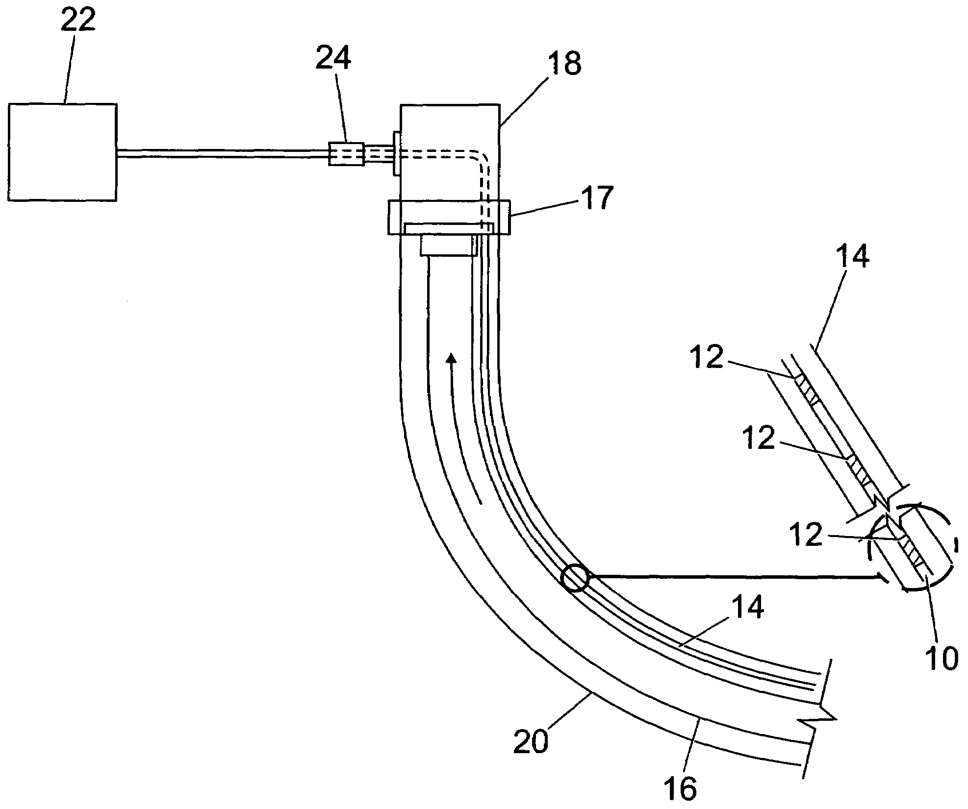
[0049]When a fiber 10 containing FBGs 12 as described above is deployed downhole, an interferometer can be used to measure the acoustic signal between each successive FBG 12. If, for example, a sensor system comprising 20 FBGs 12 are present on a deployed fiber 10, separate acoustic measurements can be made of the 19 sections between these FBGs 12. For any given period of time, an “acoustic profile” can therefore be created for the section of the well across which the FBGs 12 are deployed.

[0050]This is of interest because aspects of the acoustic signal such as the frequency components and their amplitude, will be a function of parameters such as the fluid type and flow regime of the flow past the sensor system. For given types of fluids, flow regimes and flow patterns can be characterised in terms of ...

embodiment 2

Sand Detection

[0051]One or more embodiments in accordance with the second aspect of the present invention will now be described.

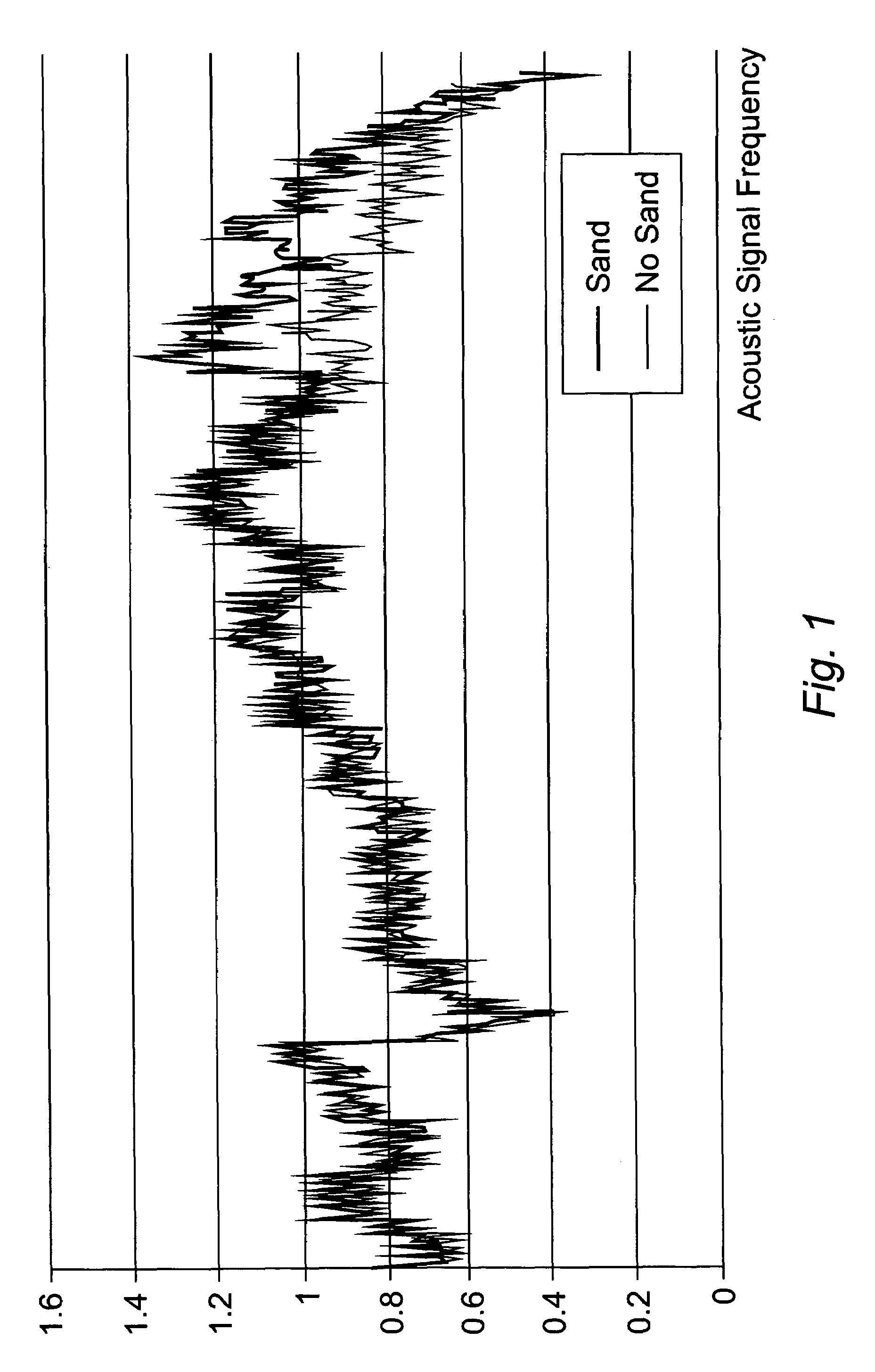
[0052]Sand flowing with the production fluid will generate noise as it impinges upon any restriction or otherwise comes in contact with any solid object, such as the wall of the production tubing 16. In relation to the production of clean fluids, sand-contaminated fluids generate discernible high-frequency components of the flow noise.

[0053]When an FBG 12 sensor system is deployed as described above, spectral analysis of the acquired acoustic signal can be used, particularly when referenced to an initial ‘baseline’ data set, to identify sand production or flow past the sensor.

[0054]FIG. 1 illustrates the signals received from such a deployed optical fiber 10 when the acoustic frequency is measured and analysed at two different points in the well where the dark trace shows the frequency signals received from a first FBG 12 and the lighter colour trace shows ...

embodiment 3

Identification and Location of Localized Events

[0055]One or more embodiments in accordance with the third aspect of the present invention will now be described.

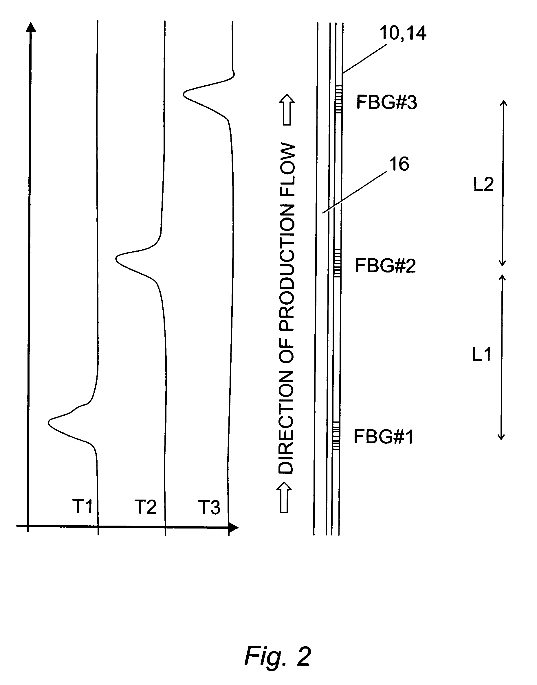
[0056]An acoustic profile can also be used to identify the presence of flow behind casing 20 or in the annulus between the tubing 16 and the casing 20 because such flow will generate an acoustic signal. When a well is provided with an optical fiber 10 carrying FBGs 12 or is otherwise instrumented as described above is shut in (not flowing), or is flowing at a low rate, or when a measurement is compared to a baseline reference survey, acoustic events detected across a particular section, but not across the rest of the instrumented section, are indicative of localised events.

[0057]Acoustic activity when the well is shut in is an indication of possible flow behind the tubing, or from tubing 16 to annulus (or vice versa).

[0058]Similarly, a leak in the tubing 16 will generate noise. A leak may not be easily detectable on a thermal...


PUM

PropertyMeasurementUnit
frequenciesaaaaaaaaaa
frequencyaaaaaaaaaa
flow velocityaaaaaaaaaa

Abstract

Methods of monitoring various downhole conditions are described, including a system for determining and / or identifying the flow of fluid in a well, determining sand production in a well, identifying localized events in a well, determining the apparent flow velocity of fluid flowing through a downhole conduit, and / or monitoring the strain in downhole tubulars. These determinations may be made by monitoring signals received from one or more sensors located in a well and analysing the signals, such as their frequency and timing.

Description

FIELD OF THE INVENTION[0001]The present invention relates to methods of monitoring downhole conditions in oil and / or gas wells and arrangements of apparatus therefor and more particularly but not exclusively relates to the use of fiber optic or electronic monitoring methods for oil and / or gas wells.BACKGROUND OF THE INVENTION[0002]Conventionally, it is known to conduct “noise log” operations in oil / gas wells. The noise log tool is an instrument sensitive to acoustic signals and is run into a well on the end of an electrical cable attached to, or contained within a wireline, in order to move it past zones of interest.[0003]Accordingly, as the noise log tool is drawn past the zones of interest, anomalies or differences from a baseline log (i.e. a log already conducted) can be used to infer information on the flow of the production fluids (i.e. the oil and / or gas) passing up the well from the production zones. Such conventional noise log technology, however, provides only a “one-shot” ...

Claims


Application Information

Patent Timeline
Patent Type & Authority Patents(United States)
IPC IPC(8): E21B47/10G01F1/7086E21B47/00E21B47/12G01F1/704G01F1/7082G01F1/74G01L1/25G06F19/00
CPCE21B47/0006E21B47/102E21B47/123G01F1/7044G01F1/7082G01F1/7086G01F1/74G01N2291/02827G01N2291/02881E21B47/007E21B47/113E21B47/135G01F1/66G01L1/255G01F1/7084G01L1/25G01N29/07E21B47/107
Inventor BLACKLAW, DAVID WILLIAM
Owner WELLDYNAMICS INC
Why Eureka
Try Eureka