Supporting seat for supporting weight of heat dissipating fins to avoid deformation of heat dissipating tubes extending through the heat dissipating fins

a technology of heat dissipating fins and supporting seats, which is applied in the direction of lighting and heating apparatus, instruments, and semiconductor/solid-state device details, etc., can solve the problems of troublesome, economic inefficiency, and deformation of heat dissipating tubes

Active Publication Date: 2008-04-15
CHEMTRON RES
View PDF7 Cites 8 Cited by
  • Summary
  • Abstract
  • Description
  • Claims
  • Application Information

AI Technical Summary

Benefits of technology

[0006]The primary objective of the present invention is to provide an improved supporting seat to support weight of the heat dissipating fins such that the weight of the heat dissipating fins will not fall directly on top of the heat dissipating tubes and the heat dissipating tube will maintain intact after a long period of time.
[0007]In order to accomplish the aforementioned objective, the supporting seat of the present invention includes a base with two flanges respectively extending from two opposed sides of the base to be securely connected to a heat dissipating plate of a heat sink, two arms extending upward between the two flanges, two engagement plates respectively formed on a free end of a corresponding arm and multiple through holes defined through each of the engagement plate for extension of the heat dissipating tubes. Because the engagement plate are securely connected to bottom faces of the heat dissipating fins and the base is securely connected to the base of the supporting seat, the heat dissipating tubes are protected from deformation.

Problems solved by technology

However, after a long period of time using the heat dissipating structure, the heat dissipating tubes will be deformed due to the weight of the heat dissipating fins on top of the heat dissipating tubes.
Therefore, after a long period of time applying the heat dissipating fins on top of the heat dissipating tubes, the heat dissipating tubes gradually deform and eventually the entire heat sink is damaged and the operator needs to replace the damaged heat sink with a new one, which is quite troublesome and economic inefficient.

Method used


Image

  • Supporting seat for supporting weight of heat dissipating fins to avoid deformation of heat dissipating tubes extending through the heat dissipating fins
  • Supporting seat for supporting weight of heat dissipating fins to avoid deformation of heat dissipating tubes extending through the heat dissipating fins
  • Supporting seat for supporting weight of heat dissipating fins to avoid deformation of heat dissipating tubes extending through the heat dissipating fins

Examples


Embodiment Construction

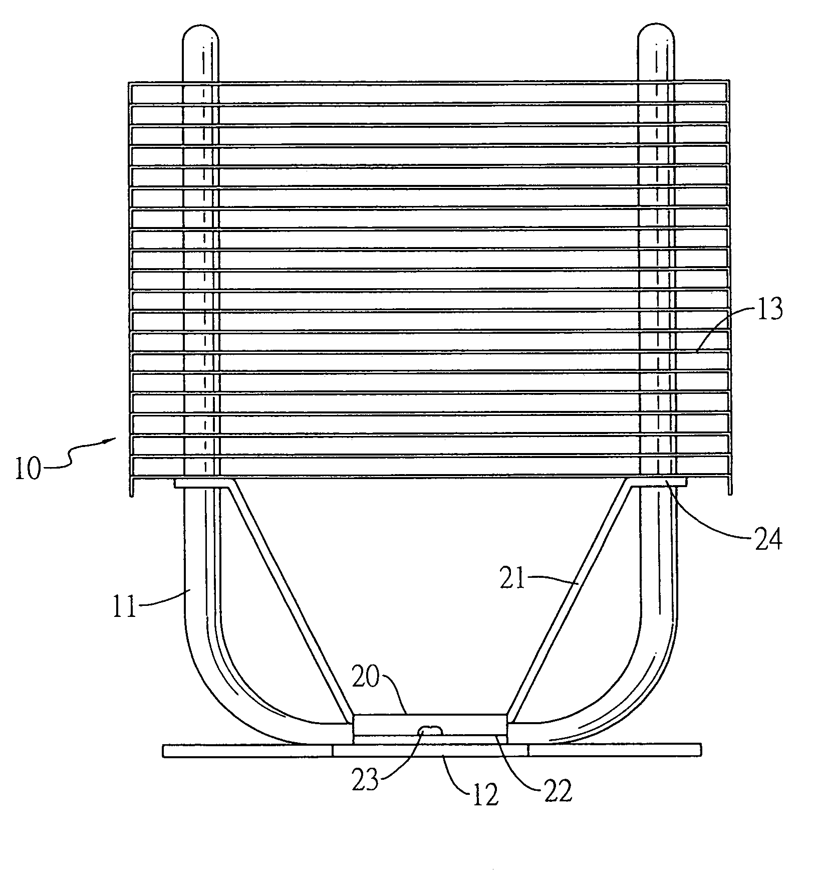
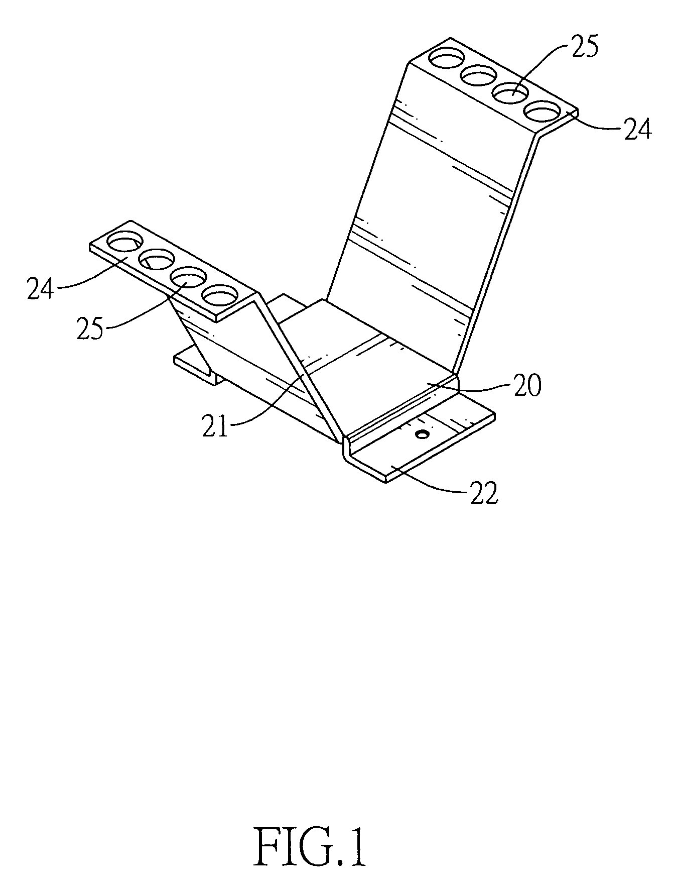
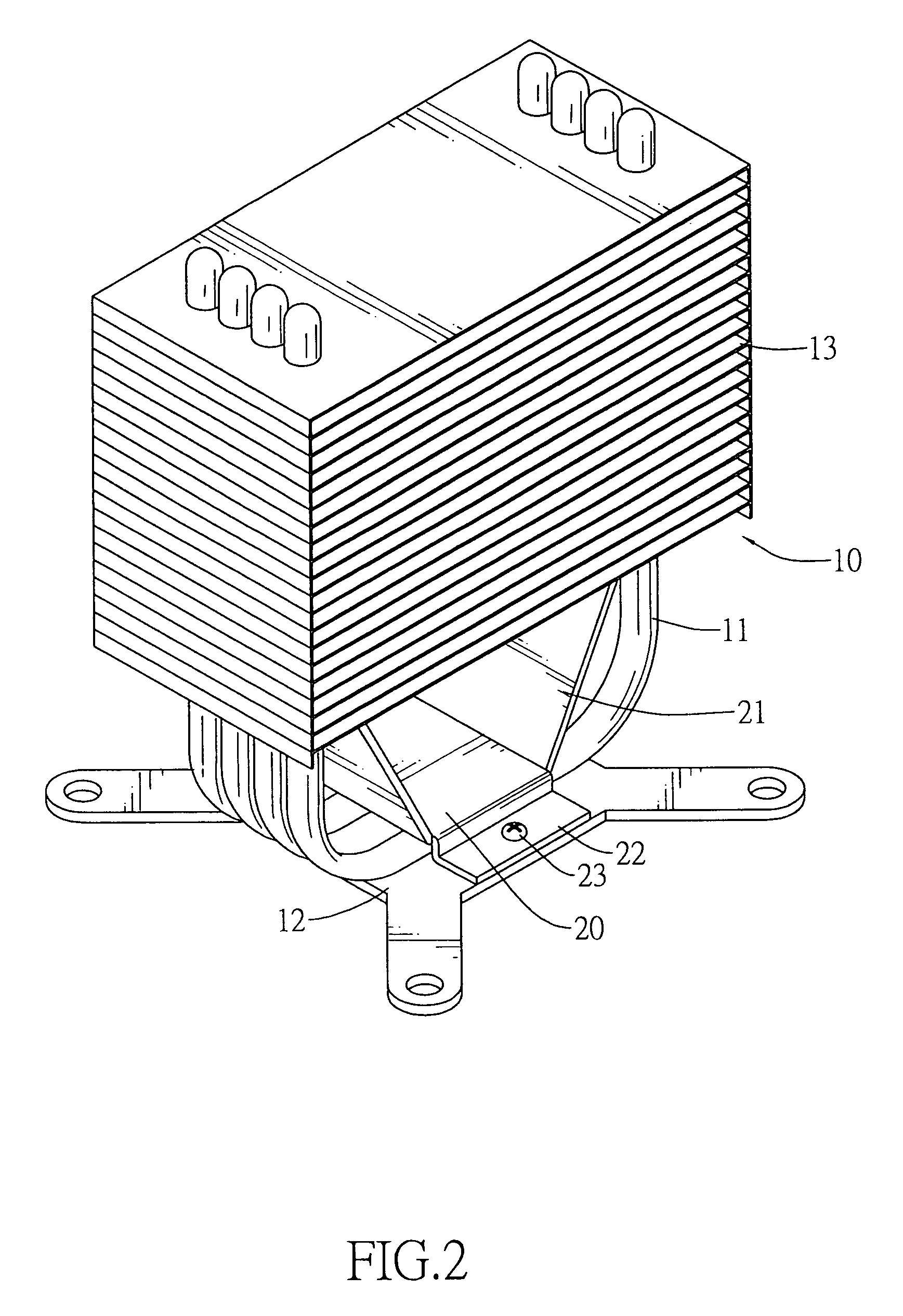
[0013]With reference to FIG. 1, it is noted that the supporting seat in accordance with the present invention includes a base (20), two arms (21) respectively extending from two opposed sides of the base (20) and being oblique relative to the base (20), two flanges (22) respectively extending from two opposed sides of the base (20) between the two arms (21), two engagement plates (24) respectively formed on a free end of a corresponding arm (21) and multiple through holes (25) defined through each of the engagement plates (24).

[0014]With reference to FIGS. 2 and 3, when the supporting seat of the present invention is employed in a heat sink (10) having a heat conducting plate (12) to be connected to a heat generating source, i.e. CPU, multiple U-shaped heat dissipating tubes (11) securely connected to the heat conducting plate (12) and multiple heat dissipating fins (13) each securely connected to the heat dissipating tubes (11), the base (20) is first connected to the heat conducti...


PUM


Abstract

A supporting seat includes a base adapted to be securely connected to the heat conductive plate, two arms extending obliquely from the base from two opposed sides of the base, two engagement plates each formed on a free end of a corresponding arm and adapted to engage with a bottom face of a lowermost one of the heat dissipating fins and multiple through holes defined through each of the two engagement plates for extension of the heat dissipating tubes. Weight of the heat dissipating fins is supported and deformation of the heat dissipating tubes is prevented.

Description

BACKGROUND OF THE INVENTION[0001]1. Field of the Invention[0002]The present invention relates to a supporting seat, and more particularly to a supporting seat for supporting weight of heat dissipating fins to avoid deformation of heat dissipating tubes which extend through the heat dissipating fins.[0003]2. Description of the Prior Art[0004]In order to effectively dissipate heat generated by CPU (central processing unit), a heat sink normally is provided with multiple heat dissipating fins and multiple heat dissipating tubes respectively extending through the heat dissipating fins. Each of the heat dissipating tubes is filled with a kind of working fluid to absorb heat from the CPU. After the heat from the CPU is absorbed by the working fluid in the heat dissipating tubes, a portion of the working fluid becomes vapor and flows to different areas in the heat dissipating tubes to conduct heat exchange. Once the heat exchange is conducted with air outside the heat dissipating tubes, th...

Claims


Application Information

Patent Timeline
Patent Type & Authority Patents(United States)
IPC IPC(8): F28D15/00H05K7/20G06F1/20H01L23/367H01L23/427H01L23/467
CPCH01L23/3672H01L23/427H01L23/467H01L2924/0002H01L2924/00
Inventor HSU, TSUNG-JUIHSU, YING-LIN
Owner CHEMTRON RES
Why Eureka
Try Eureka