
Clamping force sensor system

a sensor system and pressure sensor technology, applied in the field of pressure sensor system, can solve the problems of inaccurate data, low accuracy of conventional meter 11/b>, and spring inside the meter subject to elastic fatigue, and achieve the effect of rapid solution

Inactive Publication Date: 2008-04-15
LEE TONY
View PDF11 Cites 4 Cited by
  • Summary
  • Abstract
  • Description
  • Claims
  • Application Information

AI Technical Summary

Benefits of technology

[0013]The clamping force sensor system in accordance with the present invention provides a rapid solution for obtaining and displaying the clamping force without the troublesome use of a chart.

Problems solved by technology

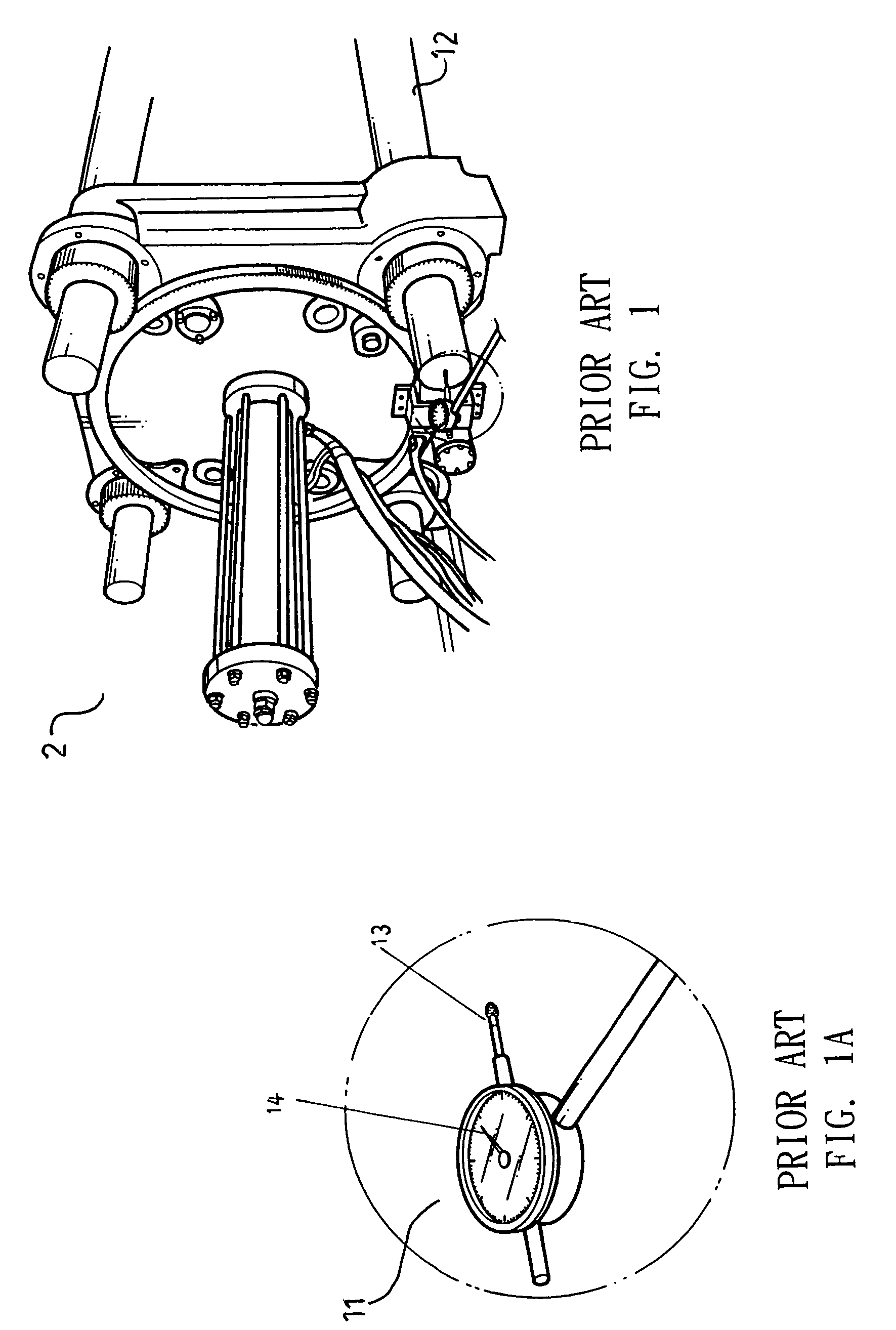
However, the conventional meter 11 has low accuracy, and the spring inside the meter is subject to elastic fatigue after being used over a long time.
Errors might be caused due to different observation angles and personal subjective judgment or negligence, leading to inaccurate data.
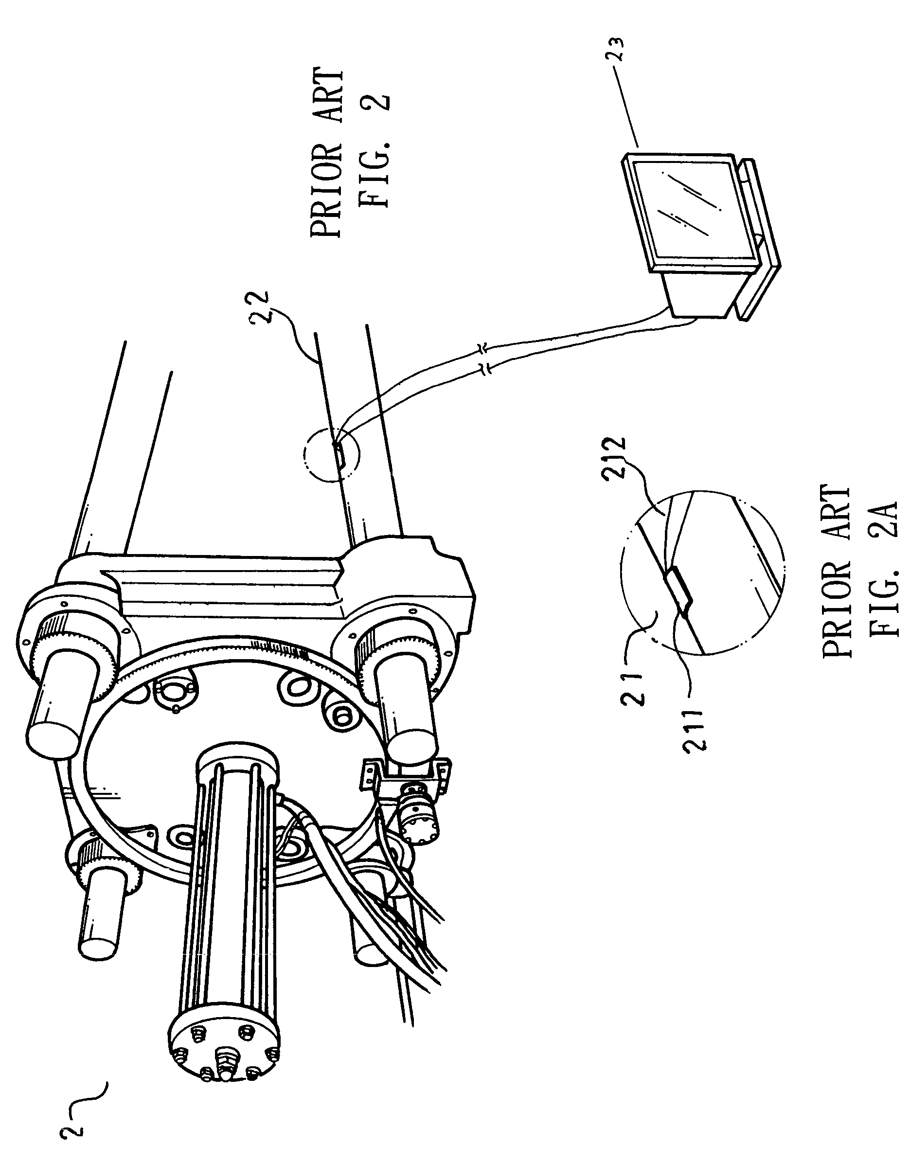
However, the costly high-precision strain meter 21 must be discarded, for the sensing element 211 is damaged when it is removed from the outer surface of the tie bar 22.
Further, it is troublesome, time-consuming, and difficult to adhere the sensing elements to the tie bars 22 at uniform angle and tightness, and therefore have adverse influence on the measurements.
Although the clamping force can be obtained by converting the electric signal into the corresponding value in terms of stretch and then checking the Yong's modulus and a load / strain chart, the procedures are troublesome and time-consuming.

Method used


Image

  • Clamping force sensor system
  • Clamping force sensor system
  • Clamping force sensor system

Examples


Embodiment Construction

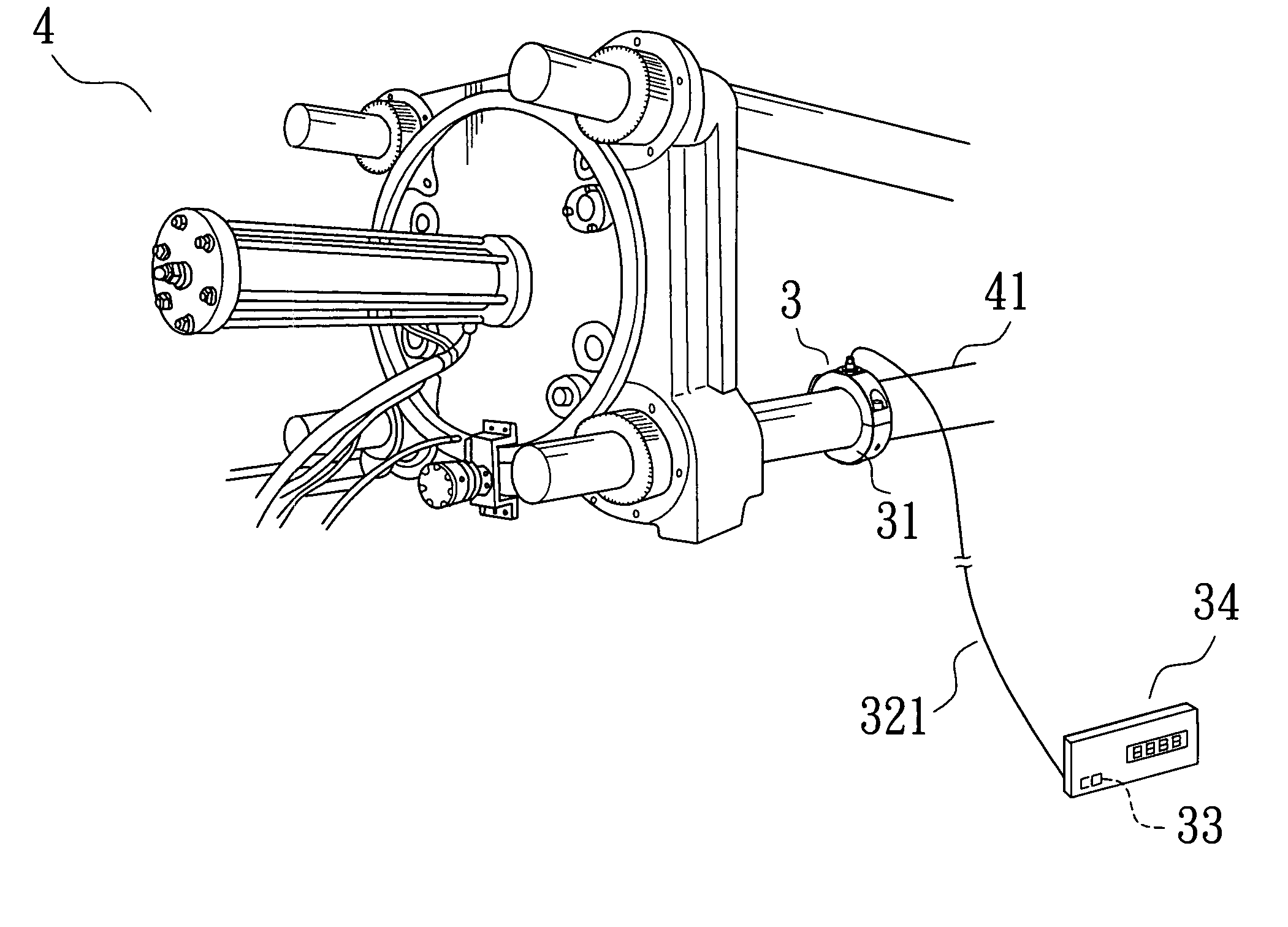
[0022]Referring to FIGS. 3 through 5, a clamping force sensor system in accordance with the present invention comprises a clamping force sensor device 3, a signal-converting program carrier 33, and an output device 34. The clamping force sensor device 3 comprises a body 31 and at least one senor 32. In this example, the body 31 is annular and mounted around a tie bar 41 of a forming machine 4. Nevertheless, the body 31 can be of any other type that can be fixed on the circumference of the tie bar 41. The body 31 includes at least one compartment 311 for receiving a soft pad 312. The pad 312 includes one or more through-holes 313 through which one or more signal lines 321 extend.

[0023]In this example, there are two sensors 32 coupled to the body 31. Each sensor 32 has a portion exposed outside of the body 31. In a case that the body 31 is annular, the portion of each sensor 32 is exposed to an inner side of the body 31. Signal lines 321 extend from each sensor 32 to the signal-conver...


PUM

PropertyMeasurementUnit
mold-clamping forceaaaaaaaaaa
clamping forcesaaaaaaaaaa
pressureaaaaaaaaaa

Abstract

A clamping force sensor system includes a clamping force sensor device, a signal-converting program carrier, and an output device. The clamping force sensor device includes a body mounted to a tie bar of a forming machine. The clamping force sensor device further includes a sensor mounted to the body, with a portion of the sensor exposed outside of the body. The signal-converting program carrier is electrically connected to the sensor by at least one signal line. The signal-converting program carrier includes a built-in program for converting a signal from the at least one signal line into a mold-clamping force. The output device is electrically connected to the signal-converting program carrier for outputting the mold-clamping force.

Description

BACKGROUND OF THE INVENTION[0001]1. Field of the Invention[0002]The present invention relates to a clamping force sensor system. More particularly, the present invention relates to a clamping force sensor system that is capable of detecting and displaying clamping forces.[0003]2. Description of the Related Art[0004]In mold-clamping operation of a typical injection molding machine or die casting machine, plastic material is fed into a mold chamber of a mold, and a movable clamping cap is moved to carry out opening / closing of the mold. The pressure applied to the mold decides formation precision of the plastic material whereas the product quality largely depends on the evenness of the clamping forces. Hence, detection of the clamping forces is required and adjustments based on the measurement results may proceed.[0005]Four tie bars are used in a typical injection molding machine or die casting machine of either vertical type or horizontal type. FIGS. 1 and 1A of the drawings illustrat...

Claims


Application Information

Patent Timeline
Patent Type & Authority Patents(United States)
IPC IPC(8): B29C45/77B29C45/76G01L1/04
CPCB29C45/7653B29C2945/76013B29C2945/76234B29C2945/76391
Inventor LEE, TONY
Owner LEE TONY
Learn More