Female connector, female connector mounting structure, and method of mounting female connector to substrate

a technology of female connectors and mounting structures, applied in the direction of coupling device details, fixed connections, coupling device connections, etc., can solve the problem of difficulty in insertion of solder into male terminal insertion paths

Inactive Publication Date: 2008-04-15
KK TOKAI RIKA DENKI SEISAKUSHO +1
View PDF9 Cites 33 Cited by
  • Summary
  • Abstract
  • Description
  • Claims
  • Application Information

AI Technical Summary

Benefits of technology

[0007]In view of the aforementioned, an object of the present invention is to provide a female connector mounting structure in which it is difficult for solder to enter into a male terminal insertion path at an inner side of a female connector.
[0014]As described above, the female connector mounting structure of the present invention has the excellent effect that it is difficult for solder to enter into a male terminal insertion path at an inner side of a female connector.

Problems solved by technology

Therefore, it is difficult for solder to enter into a male terminal insertion path at an inner side of the female connector.

Method used


Image

  • Female connector, female connector mounting structure, and method of mounting female connector to substrate
  • Female connector, female connector mounting structure, and method of mounting female connector to substrate
  • Female connector, female connector mounting structure, and method of mounting female connector to substrate

Examples


Embodiment Construction

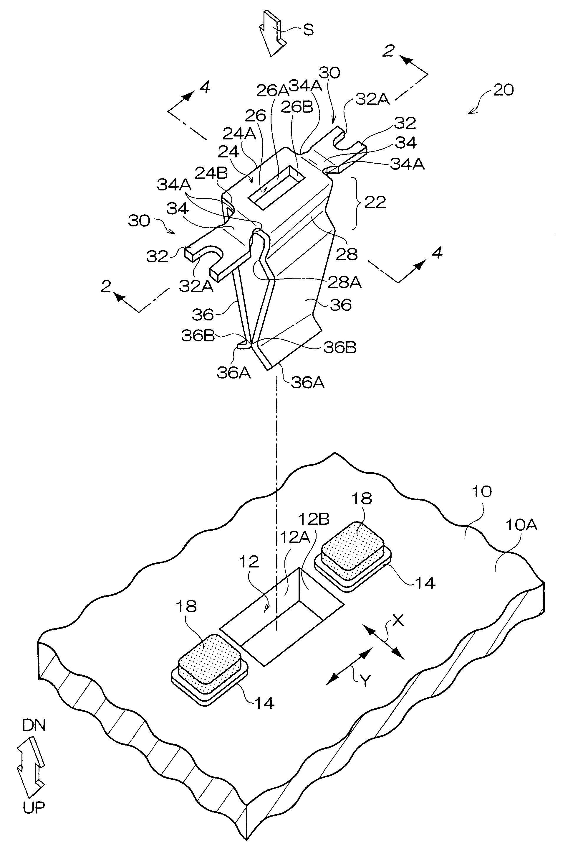
[0021]An embodiment of a female connector mounting structure in the present invention will be described on the basis of the drawings. Note that arrow UP in the drawings indicates the direction facing from the reverse surface toward the obverse of a substrate, and arrow DN indicates the direction facing from the obverse toward the reverse surface of the substrate.

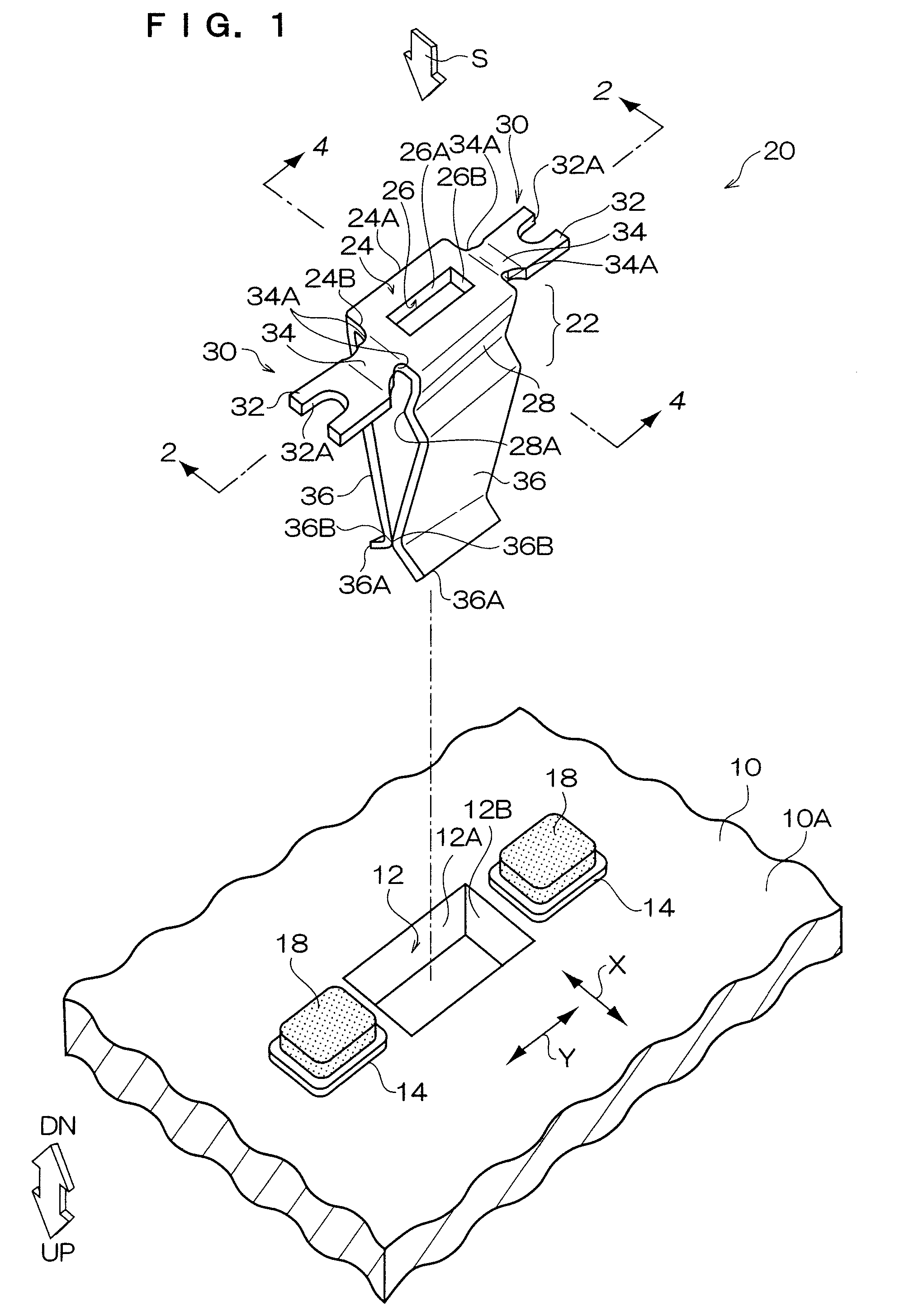
[0022]A substrate 10, and a single pole female connector 20 which serves as a female connector and which is mounted to the substrate 10, are shown in FIG. 1.

[0023]As shown in FIG. 1, a through-hole 12, which serves as a hole and which passes through the obverse and reverse of the substrate 10, is formed in the substrate 10. The configuration of the through-hole 12 in plan view is rectangular. The through-hole 12 has long side portions 12A and short side portions 12B, and is for insertion of the single pole female connector 20 (details will be described later). The dimensions of the long side portions 12A and short side porti...


PUM


Abstract

A single pole female connector has: a mounting base portion in which is formed a terminal insertion hole into which a male terminal can be inserted; an extending portion extending outwardly from the mounting base portion; and a terminal contacting portion which extends from a peripheral edge of the mounting base portion in a direction substantially orthogonal to a plate portion, and which is formed so as to be able to nip the male terminal. The extending portion is electrically connected by being reflow soldered to a land at a reverse surface of the substrate. It is difficult for cream solder to enter into a male terminal insertion path at an inner side of the female connector.

Description

CROSS-REFERENCE TO RELATED APPLICATION[0001]This application claims priority under 35 USC 119 from Japanese Patent Application No. 2005-331710, the disclosure of which is incorporated by reference herein.BACKGROUND OF THE INVENTION[0002]1. Field of the Invention[0003]The present invention relates to a female connector which is disposed at a substrate, a female connector mounting structure, and a method of mounting a female connector to a substrate.[0004]2. Description of the Related Art[0005]In mounting a female connector, structures are known in which soldering is carried out in order to securely mount the female connector to a printed substrate (see, for example, Japanese Patent Application Laid-Open (JP-A) No. 11-67298). In this mounting, in a state in which a terminal of a female connector is inserted into a mounting hole of a printed substrate, molten solder is jetted and soldering is carried out.[0006]In this conventional female connector mounting structure, it is easy for sol...

Claims


Application Information

Patent Timeline
Patent Type & Authority Patents(United States)
IPC IPC(8): H01R12/00H01R12/58
CPCH01R13/111H01R13/113H01R12/707H01R12/57H01R12/58
Inventor MINOURA, AKIHIROTAKEUCHI, TOSHIHIROSUZUKI, NORIHITOINOUE, SHUICHIKAWAGUCHI, AKIRA
Owner KK TOKAI RIKA DENKI SEISAKUSHO
Why Eureka
Try Eureka