Apparatus and method for digital wireless communications

a digital wireless communication and apparatus technology, applied in the direction of synchronisation signal speed/phase control, multiple modulation transmitter/receiver arrangement, phase-modulated carrier system, etc., can solve the problem of deteriorating bit error rate characteristic in signal to noise ratio, affecting the power efficiency of power amplifiers, and affecting the accuracy of estimating reference phases. problem, to achieve the effect of improving the bit error rate characteristic, reducing the jitter of symbol synchronization, and reducing the ji

Inactive Publication Date: 2008-04-15
TIANMA MICRO ELECTRONICS CO LTD
View PDF23 Cites 47 Cited by
  • Summary
  • Abstract
  • Description
  • Claims
  • Application Information

AI Technical Summary

Benefits of technology

[0010]It is an objective of the present invention to provide an apparatus and method for digital wireless communications capable of improving the accuracy in estimating the reference phase and amount of frequency offset when the receiver (demodulation side) carries out quasi-coherent detection and improving the bit error rate characteristic in the signal to noise ratio.
[0012]This makes it possible to suppress deterioration of the accuracy in estimating the reference phase and amount of frequency-offset using pilot symbols in quasi-coherent detection with symbols whose symbol synchronization is not completely established and improve the bit error rate characteristic in the signal to noise ratio.
[0014]This apparatus can not only suppress deterioration in the accuracy in estimating the reference phase, amount of frequency offset by a pilot symbol in quasi-coherent detection with symbols whose symbol synchronization is not completely established, but also improve the bit error rate characteristic in the signal to noise ratio without deteriorating the power efficiency of the power amplifier on the transmitting side.

Problems solved by technology

However, during quasi-coherent detection with such a frame configuration with one pilot symbol inserted for every few information symbols, symbol synchronization gets the jitters.
Therefore, in quasi-coherent detection with symbols whose symbol synchronization is not completely established, the accuracy in estimating the reference phase, amount of frequency offset and amount of amplitude distortion using pilot symbols deteriorates.
This results in deterioration of a bit error rate characteristic in the signal to noise ratio.
This deteriorates the error rate.
However, when detected at time 2 when the time offset occurred, the pilot symbol signal has an error from the pilot symbol signal point, and therefore the accuracy in estimating the phase, amplitude variation and frequency offset deteriorates.

Method used


Image

  • Apparatus and method for digital wireless communications
  • Apparatus and method for digital wireless communications
  • Apparatus and method for digital wireless communications

Examples


embodiment 1

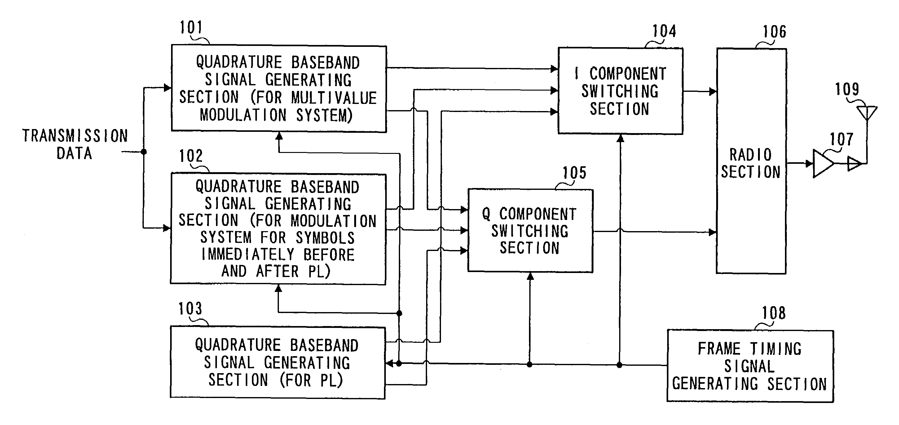
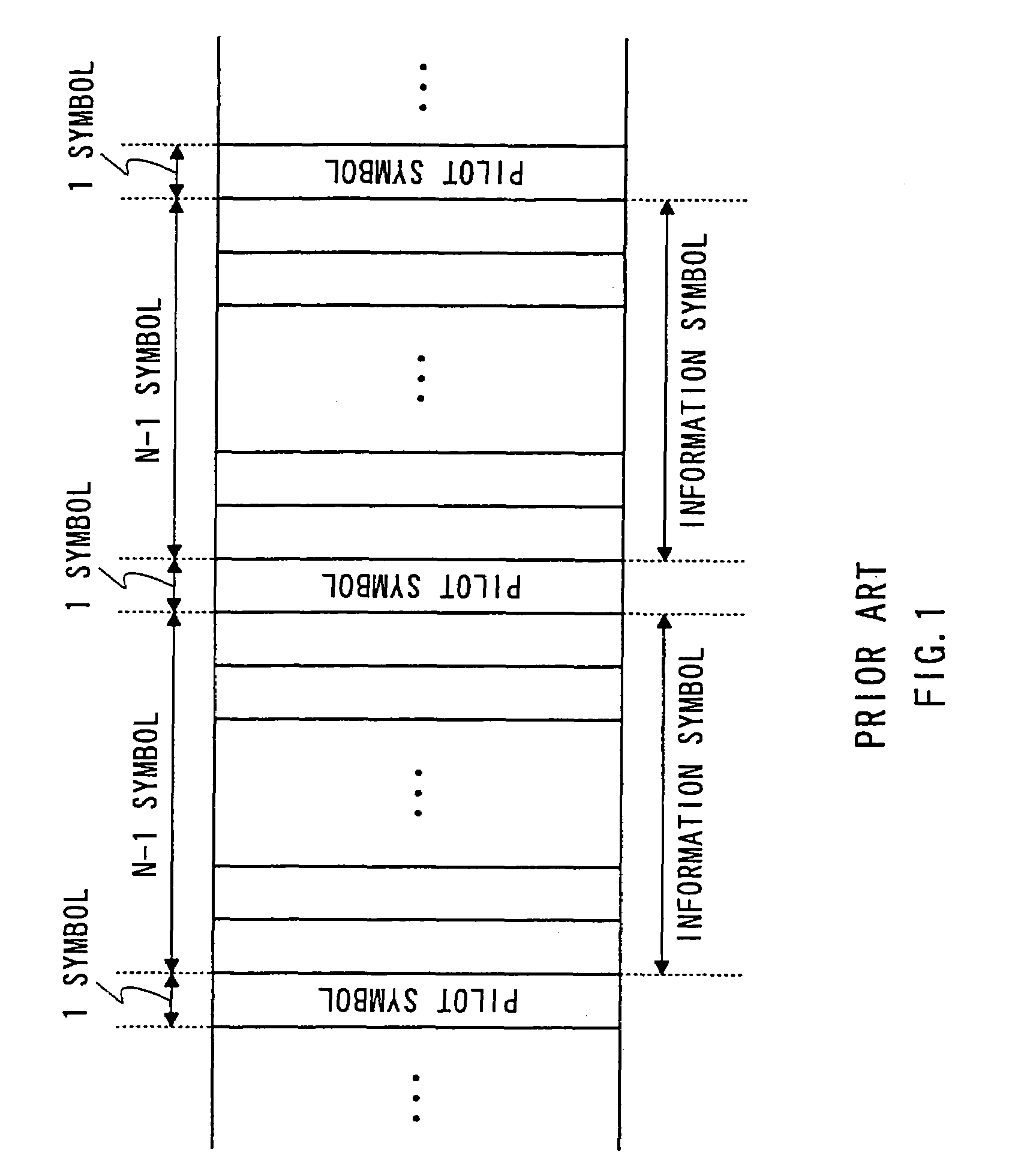
[0050]FIG. 4 is a block diagram showing a configuration of the transmitter side of a digital wireless communication apparatus of the present invention. FIG. 5 is a block diagram showing a configuration of the receiver side of a digital wireless communication apparatus of the present invention. FIG. 6A is a diagram showing a frame configuration used in the digital wireless communication apparatus of the present invention.

[0051]The following is an explanation of a case where the modulation type used is a multivalue modulation type.

[0052]On the transmitter side shown in FIG. 4, transmission data are sent to quadrature baseband signal generating section (for multivalue modulation type) 101 and quadrature baseband signal generating section (for modulation type for symbols immediately before and after PL) 102. Frame timing signal generating section 108 generates a frame timing signal at timing indicating a frame configuration shown in FIG. 6A and outputs the frame timing signal to quadrat...

embodiment 2

[0070]FIG. 7 shows a signal space diagram on the in-phase I-quadrature Q plane according to a 16APSK modulation type, which is an example of a multivalue modulation type with 8 or more values, indicating pilot symbol signal points and signal points of one symbol before and after the pilot symbols. In FIG. 7, reference codes 401 indicate signal points according to the 16APSK modulation type, reference code 402 indicates the pilot symbol signal point and reference codes 403 indicate the signal points of each one symbol immediately before and after the pilot symbol. Furthermore, reference code 404 is a virtual line connecting the pilot symbol signal point and the origin on the I-Q plane, and two or more signal points 403 of each one symbol immediately before and after the pilot symbol are placed on virtual line 404 connecting the pilot symbol signal point 402 and the origin.

[0071]FIG. 8 shows a frame configuration example of symbols and pilot symbols modulated according to the 16APSK m...

embodiment 3

[0075]FIG. 9 shows a signal space diagram according to a multivalue quadrature amplitude modulation (QAM) system with 8 or more values on the in-phase I-quadrature Q plane and shows pilot symbol signal point and signal points of each one symbol immediately before and after the pilot symbol. In FIG. 9, reference codes 501 indicate the signal points according to the multivalue QAM system, reference code 502 indicates a pilot symbol signal point and reference codes 503 indicate signal points of each one symbol immediately before and after the pilot symbol. Reference code 504 is a virtual line connecting the pilot symbol signal point and the origin on the I-Q plane. Two or more signal points 503 of each one symbol immediately before and after the pilot symbol are placed on virtual line 504 connecting pilot symbol signal point 502 and the origin.

[0076]FIG. 10 shows a frame configuration example of symbols and pilot symbols modulated according to the multivalue QAM system with 8 or more v...


PUM


Abstract

A digital wireless communication apparatus includes a first modulator that modulates a pilot symbol according to a first modulation scheme, and a second modulator that modulates specific symbols according to a second modulation scheme, the second modulation scheme being different than the first modulation scheme. A third modulator modulates symbols other than the pilot symbol and the specific symbols according to a third modulation scheme, the third modulation scheme being different than the first and second modulation schemes. A timing controller controls timing such that the specific symbols are inserted immediately before and after the pilot symbol. The signal points of the specific symbols are allocated on an imaginary line that connects the origin point and a signal point of the pilot symbol on a signal space diagram.

Description

[0001]This is a Continuation of U.S. application Ser. No. 10 / 427,992, filed May 2, 2003, now U.S. Pat. No. 6,748,023 which is a continuation of U.S. application Ser. No. 09 / 482,892 (now U.S. Pat. No. 6,608,868), filed Jan. 14, 2000, the contents of which are expressly incorporated by reference herein in their entirety.BACKGROUND OF THE INVENTION[0002]1. Field of the Invention[0003]The present invention relates to an apparatus and method for digital wireless communications using a multivalue modulation type.[0004]2. Description of the Related Art[0005]In a conventional digital mobile wireless communication system, a familiar example of frame configuration method to estimate a frequency offset is described in “Terrestrial Mobile Communication 16QAM Fading Distortion Compensation Method” (Sanbe, TECHNICAL REPORT OF IEICE, B-II, Vol. J-72-B-II, No. 1, pp. 7-15, January 1989). FIG. 1 shows a frame configuration according to a 16QAM system.[0006]As shown in FIG. 1, this frame configuratio...

Claims


Application Information

Patent Timeline
Patent Type & Authority Patents(United States)
IPC IPC(8): H04L27/26H04B7/216H04L23/02H04L7/06H04L27/34
CPCH04L27/206H04L27/34H04L27/3405H04L27/3455H04L7/04H04L7/06H04L27/0008H04L2027/0087H04L2027/0093H04L2027/0024
Inventor MURAKAMI, YUTAKATAKABAYASHI, SHINICHIROORIHASHI, MASAYUKIMATSUOKA, AKIHIKO
Owner TIANMA MICRO ELECTRONICS CO LTD
Why Eureka
Try Eureka