[0007]In the airbag thus constructed, the left and right half airbags contact with each other, and a space behind the tie panel becomes small when the left and right half airbags are expanded. Therefore, when the occupant is plunged into the airbag, the airbag can receive the occupant safely without intruding excessively deep into the space.
[0009]According to the second aspect of the invention, in the airbag of the first aspect, it is preferable that the tie panel connects the
left half airbag and the right half airbag at sides thereof facing the occupant. With this configuration, when the occupant is plunged into the airbag, the tie panel supports the occupant, thereby sufficiently reducing the
impact applied to the occupant.
[0010]According to the third aspect of the invention, in the airbag of the second aspect, it is preferable that the tie panel connects the
left half airbag and the right half airbag at front ends thereof facing the occupant. With this configuration in which the tie panel is provided at the front ends of the left and right half airbags, when the occupant is plunged into the airbag, the occupant contacts the tie panel first. Accordingly, the
impact on the occupant becomes smaller at the moment when the occupant contacts the airbag. Since the tie panel absorbs
kinetic energy of the occupant, the
impact on the occupant becomes further smaller at the moment when the occupant contacts the airbag.
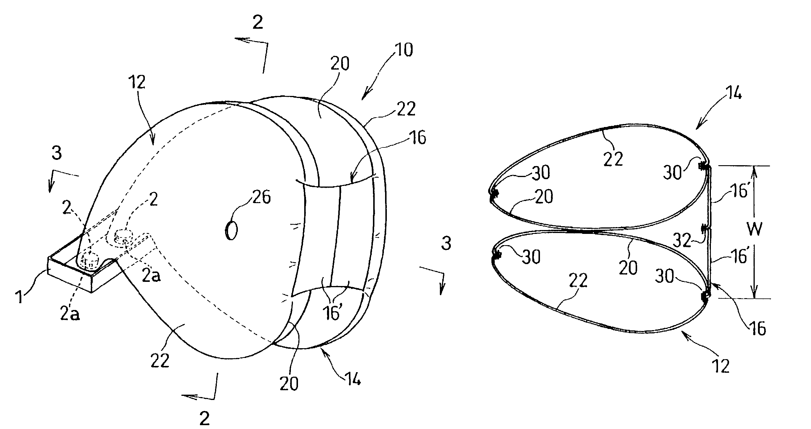
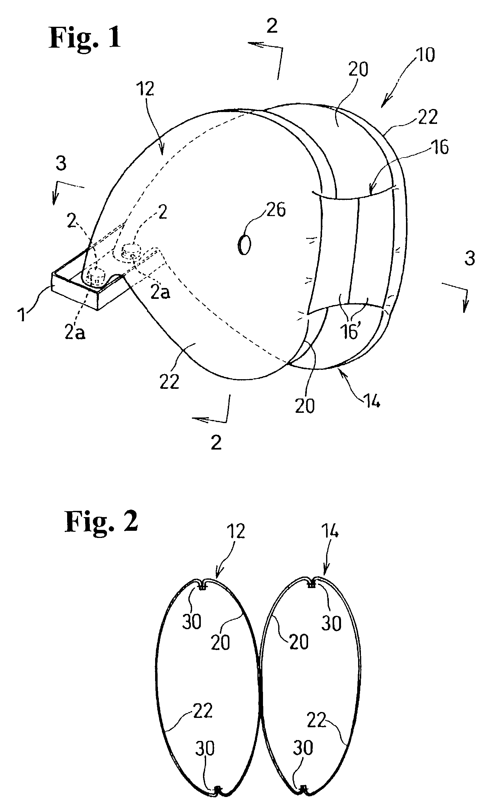
[0011]According to the fourth aspect of the invention, in the airbag of the second aspect, it is preferable that the tie panel includes an upper tie panel for connecting upper portions of the left half and the right half airbags at sides facing the occupant; and a lower tie panel for connecting lower portions of the left half and the right half airbags at sides facing the occupant. In this case, when the occupant is plunged into the inflated airbag, the upper tie panel is arranged to face a chest or head part of the occupant, and the lower tie panel is arranged to face an abdominal part of the occupant. When the chest or head and abdominal parts of the occupant contact the airbag, the upper and lower tie panels can receive the chest, head and abdominal parts relatively softly, thereby greatly reducing the impact applied to a brain or internal organs of the occupant.
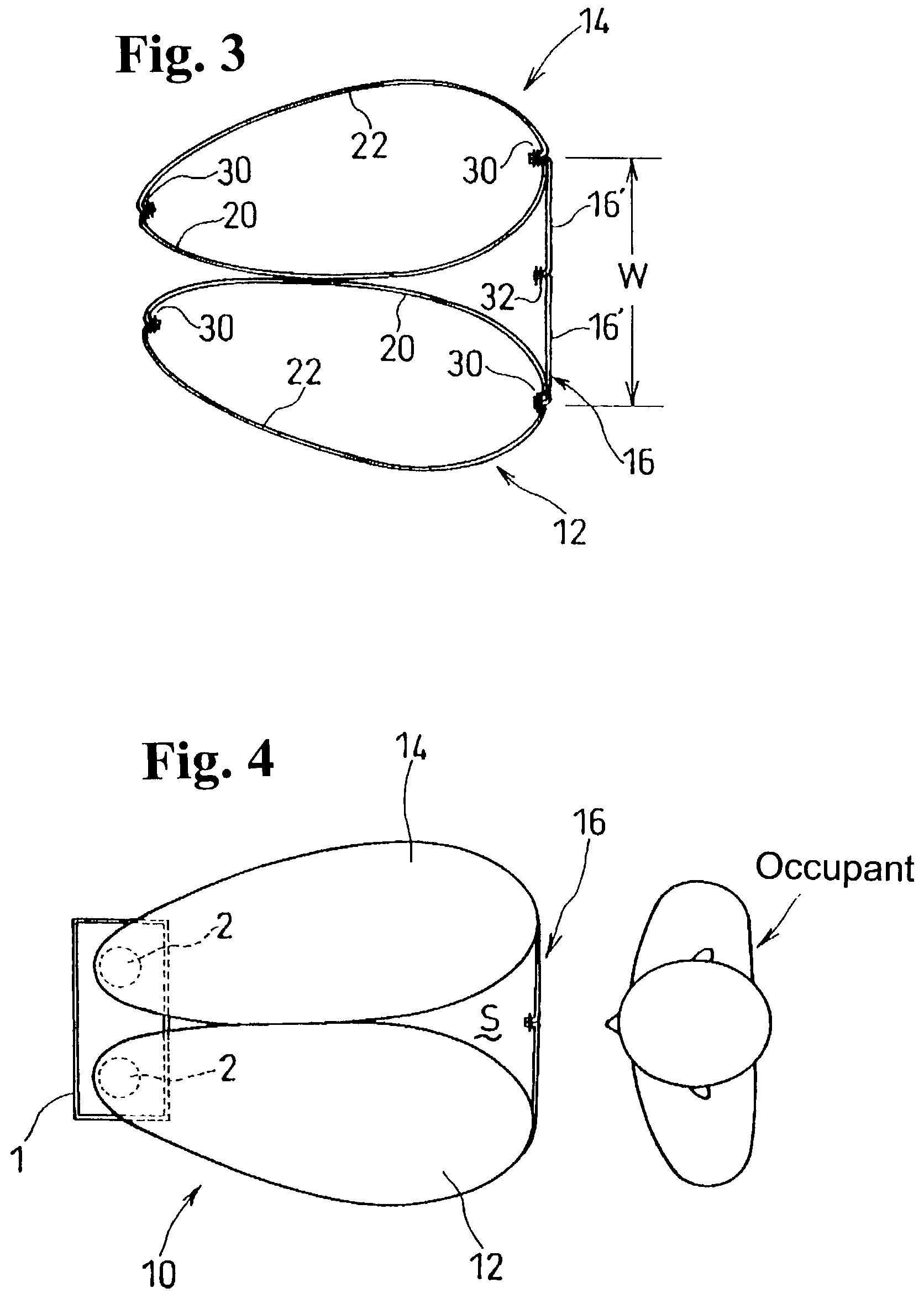
[0013]In the airbag of the present invention, it is preferable that a lateral width of the tie panel is 200 to 450 mm. With the tie panel having a 200 to 450 mm width, when the left and right half airbags are expanded, the tie panel connects the front ends of the airbags such that the front ends face the vicinity of both shoulders of an adult occupant having an
average size, and the tie panels are arranged so as to face the head and abdominal parts of the occupant. Therefore, it is possible to hold the chest or head part and the abdominal part of the occupant with the tie panels having relatively large elasticity, thereby reducing the impact applied to the occupant due to the contact with the airbag. Furthermore, the left and right half airbags contact both shoulders of the occupant to securely receive the occupant.
[0015]With the structure thus constructed, when the occupant is plunged into the left and right half airbags, it is possible to prevent buckling deformation in which the left and right half airbags move apart at central portions in the front-to-rear direction.

