Rotating member-supporting structure and rotation detecting device having the same

a technology of rotating member and supporting structure, which is applied in the direction of mechanical measurement arrangement, instruments, manufacturing tools, etc., can solve the problems of large eccentricity of rotating member and the inability to realize the required resolution, and achieve the effect of suppressing the eccentricity of rotating member and high precision

Inactive Publication Date: 2008-04-29
ALPS ALPINE CO LTD
View PDF4 Cites 8 Cited by
  • Summary
  • Abstract
  • Description
  • Claims
  • Application Information

AI Technical Summary

Benefits of technology

[0010]The present invention has been finalized in view of the drawbacks inherent in the conventional rotation detecting device, and it is an object of the present invention to provide a rotating member-supporting structure and a rotation detecting device having the same which can suppress the eccentricity of a rotating member with respect to a guide unit with high precision.
[0012]As described above, if the metallic elastic member is interposed between the rotating member and the guide unit, the central axis of the rotating member can be stably held in the center of the guide unit irrespective of the size of the clearance between the rotating member and the guide unit. In addition, if at least three portions along the circumference of the rotating member are elastically supported by the metallic elastic member, the eccentricity of the rotating member with respect to the guide unit can be suppressed with high precision. Further, if the metallic elastic member is used as the elastic member, the size, the thickness and the manufacturing cost can be reduced.
[0013]Further, in the rotating member-supporting structure, elastic member-holding units are provided in at least three places of the guide unit along the circumference to hold the metallic elastic member, which prevent the rotation of the metallic elastic member.
[0014]As described above, if the elastic member-holding units are provided in at least three places of the guide unit, positional deviation of the metallic elastic member with respect to the guide unit and dropout of the metallic elastic member from the guide unit can be prevented reliably, therefore quietness and operational stability of the rotating member-supporting structure can be enhanced.
[0016]As described above, if the elastic member-holding units are provided at regular intervals along the circumference of the guide unit, and the rotating member is elastically supported by the metallic elastic member in the intermediate portion of each of the elastic member-holding units, the rotating member can be elastically supported with respect to the guide unit evenly. Therefore, the central axis of the rotating member can be reliably held in the center of the guide unit, and the eccentricity of the rotating member with respect to the guide unit can be suppressed with high precision.
[0018]As described above, if the metallic elastic member is made of stainless steel and has a band-shape, the strength of the metallic elastic member can be increased, and the thickness and width of the metallic elastic member can be reduced. Also, the metallic elastic member can have a stable elastic characteristic. Therefore, the space efficiency between the rotating member and the guide unit can be enhanced, the size and thickness of the rotating member-supporting structure can be further reduced, and a variation in the rotation torque of the rotating member caused by a temperature change can be decreased. In addition, since a required metallic elastic member can be manufactured only by bending a band-like stainless body, the metallic elastic member and thus the rotating member-supporting structure can be manufactured at a low cost.

Problems solved by technology

However, in recent years, since high resolution of one degree or more is required in this type of the rotation detecting device, if the clearance between the guide unit and the rotating member is allowed in the range of 0.3 mm to 0.5 mm, the eccentricity of the rotating member becomes large, and it is impossible to realize required resolution.

Method used


Image

  • Rotating member-supporting structure and rotation detecting device having the same
  • Rotating member-supporting structure and rotation detecting device having the same
  • Rotating member-supporting structure and rotation detecting device having the same

Examples


Embodiment Construction

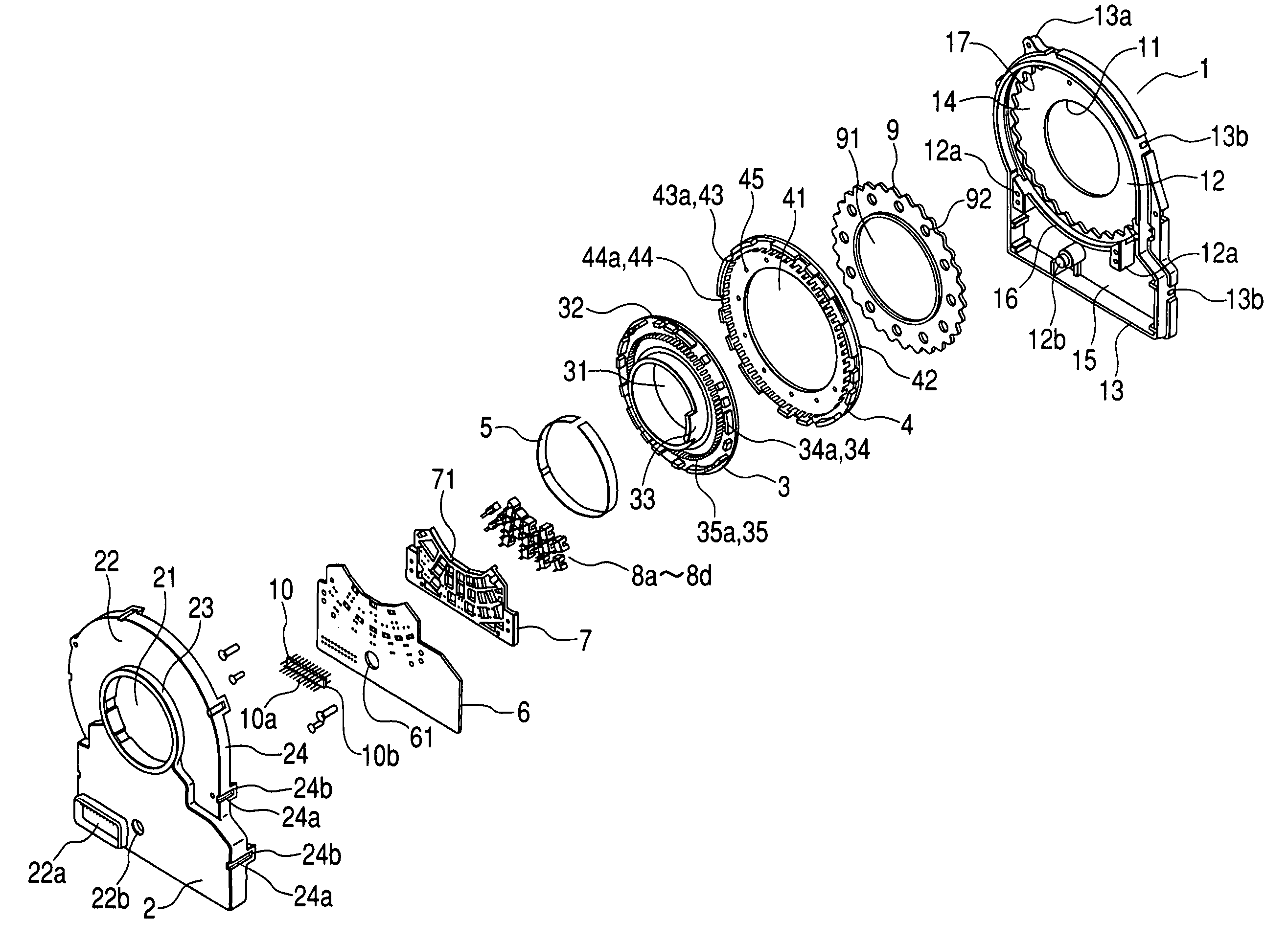
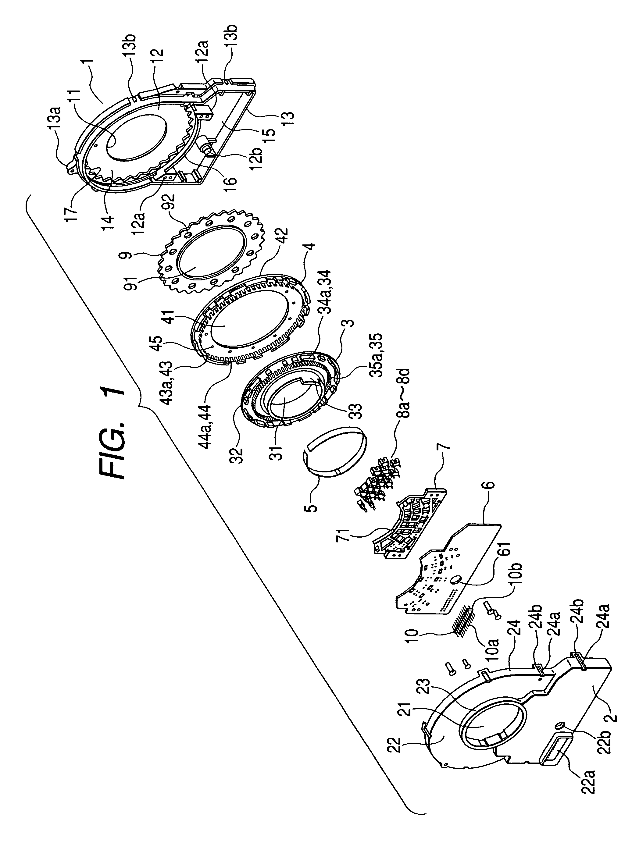
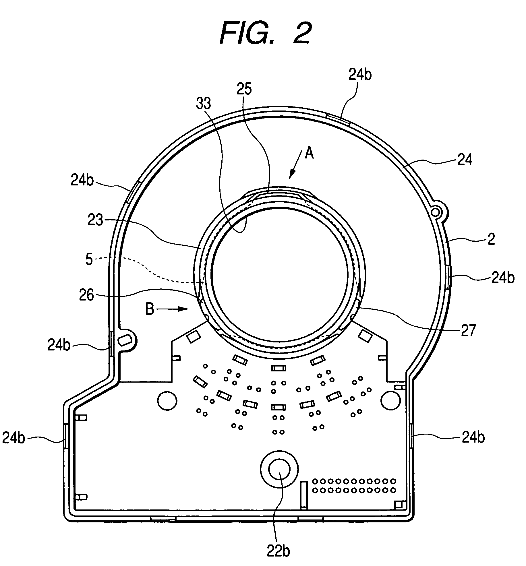
[0028]Hereinafter, an embodiment of a rotating member-supporting structure according to an aspect of the present invention will be described with reference to FIGS. 1 to 7 using an example of a code wheel-supporting structure in a rotation detecting device. FIG. 1 is an exploded perspective view of a rotation detecting device according to the present embodiment, FIG. 2 is an internal view illustrating a cover according to the embodiment, FIG. 3 is an enlarged diagram of A portion of FIG. 2, FIG. 4 is an enlarged diagram of B portion of FIG. 2, FIG. 5 is a rear view of a first code wheel according to the embodiment, FIG. 6 is a plan view illustrating a metallic elastic member according to the present embodiment, and FIG. 7 is an internal diagram of a case showing a coupling state among a planetary gear, an internal gear, and a second code wheel.

[0029]As shown in FIG. 1, the rotation detecting device according to the embodiment mainly includes a case 1; a cover 2; a first code wheel 3...


PUM

PropertyMeasurementUnit
temperatureaaaaaaaaaa
supporting structureaaaaaaaaaa

Abstract

Three elastic member-holding units are provided along the circumference of a cylindrical guide unit, which is a supporting unit of a first code wheel to hold a ring-shaped metallic elastic member, which is made of a band-like body of stainless steel or the like, and the metallic elastic member is extended to the inner circumference of the guide unit. In addition, the metallic elastic member extended to the inner circumference of the guide unit elastically supports the shaft of the first code wheel, which is a rotating member.

Description

BACKGROUND OF THE INVENTION[0001]1. Field of the Invention[0002]This application claims the benefit of priority to Japanese Patent Application No. 2004-181551 filed on Jun. 18, 2004, herein incorporated by reference.[0003]The present invention relates to a rotating member-supporting structure and a rotation detecting device having the same, or more specifically, to a means for suppressing the eccentricity of the rotating member with respect to a guide unit.[0004]2. Description of the Related Art[0005]Conventionally, as a rotation detecting device which is applied to a rudder angle sensor for a car or the like, a device is known, which includes a case-shaped attaching member on which a through-hole for a rotating member is provided, a rotating member which is held through the through-hole, a code plate which is attached to the rotating member and rotatably housed in the attaching member, and signal detecting elements which are provided inside the attaching member and operate in conju...

Claims


Application Information

Patent Timeline
Patent Type & Authority Patents(United States)
IPC IPC(8): F16H57/12G01B11/26B23P11/02G01D5/347G01D11/30
CPCG01D11/245G01D5/34738
Inventor SANO, TADASHI
Owner ALPS ALPINE CO LTD
Why Eureka
Try Eureka