
Optical recording medium and manufacturing method thereof

Inactive Publication Date: 2006-08-17
CANON KK
View PDF9 Cites 11 Cited by
  • Summary
  • Abstract
  • Description
  • Claims
  • Application Information

AI Technical Summary

Benefits of technology

[0024] The present invention provides a method of manufacturing an optical recording medium, which is capable of manufacturing a highly reliable optical recording medium, an eccentricity of each recording layer formed respectively on a plurality of sheet-like substrates may be suppressed, and which does not involve a complicated process.

Problems solved by technology

However, the conventional proposals according to the following documents have the following problems, respectively.
If the center of each substrate is not positioned with high accuracy in an optical disk, the eccentricity of the substrate may occur, which causes various inconveniences.
Thus, it is difficult to handle the sheet, which causes a problem in terms of productivity.
However, this is strictly limited to a two-layered structure, and a multi-layered (three or more layered) structure is not taken into consideration.
However, Japanese Patent Application Laid-Open No. 2003-115130 does not take punching of the sheet into consideration.
However, in the case of a multi-layered structure, it is necessary to set the thickness of each sheet to be several μm to several tens of μm, which is considered to make it difficult to hold the sheet.
This means, for example, that thin sheets cannot be laminated satisfactorily in a bonding process.
Further, according to the manufacturing method of Japanese Patent Application Laid-Open No. 2003-115130, in the same way as in International Publication No. 98 / 02875, the 2P method that is a conventionally known manufacturing method is used, and a material for light-curable resin is merely limited.
Therefore, production process is complicated, which is disadvantageous for enhancing productivity.
More specifically, the manufacturing method described in Japanese Patent Application Laid-Open No. 2002-288894 puts emphasis on the production of an optical recording medium with a two-layered structure, and is not suitable for manufacturing a multi-layered structure of three or more layers.

Method used


Image

  • Optical recording medium and manufacturing method thereof
  • Optical recording medium and manufacturing method thereof
  • Optical recording medium and manufacturing method thereof

Examples


example 1

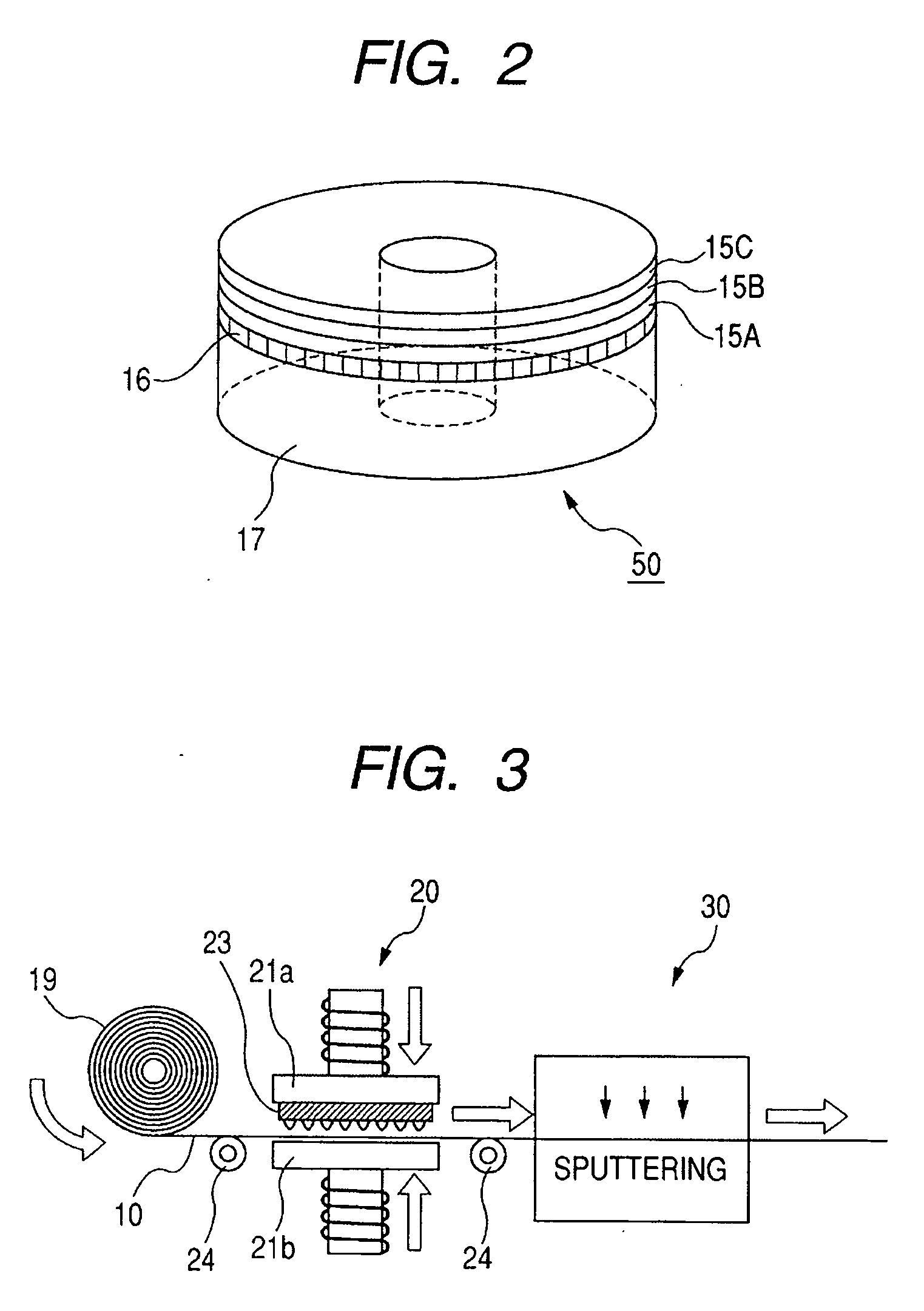
[0093] Hereinafter, a specific example of the present invention will be described with reference to FIGS. 1, 2, 3, 4A to 4C, 5, 6, and 7A to 7E.

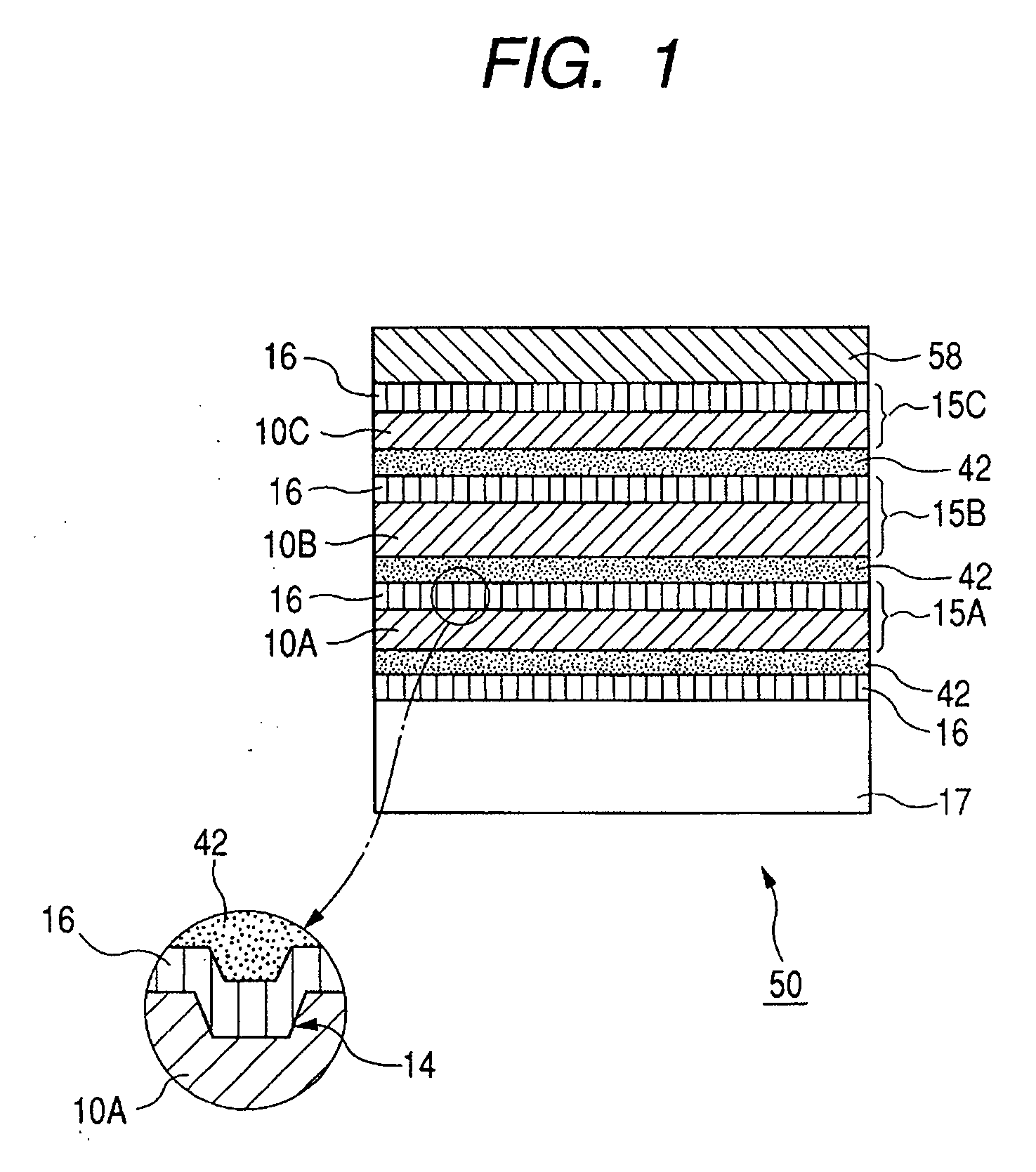
[0094] As the sheet-like substrates 10A, 10B, and 10C made of polycarbonate, those having thicknesses of 12 μm, 13 μm, and 14 μm, respectively, were prepared. A protective sheet with a thickness of 100 μm was laminated on one surface of each sheet-like substrate as a backing member.

[0095] The glass transition point of polycarbonate resin was 140° C., and the thermal deformation temperature thereof was about 120° C. Further, the temperature of the sheet-like substrates immediately after the transcription by the stamper 23 of the forming apparatus 20 was 30° C. to 40° C.

[0096] In the film-forming apparatus 30, a SiN film (reflective layer) was formed as the recording layer 16 by sputtering, and the thickness thereof was 10 nm. In the process of sputtering, a mask was used so that the alignment marks 13 were not formed.

[0097] The transmitta...

example 2

[0133] Next, the step of providing the protective layer 58 on the laminated recording medium 55 in which the laminate 50′ and the support substrate 17 are bonded together will be described in detail.

[0134]FIGS. 11A to 11D schematically show the process of forming a protective layer in the case of using a sheet 100 for forming a protective layer in a method of manufacturing an optical recording medium according to the present invention.

[0135] First, the laminated recording medium 55 was held on the holding tool 111. The protecting sheet 100 was placed in vacuum on the recording layer side of the held laminated recording medium 55 so as not to involve air and a foreign matter between the laminated recording medium 55 and the protecting sheet 100. As the protecting sheet is made of thermoplastic resin, a sheet with a thickness of 75 μm was used. A center hole was provided in the used protecting sheet, and the inner / outer diameters thereof completely covered the recording layer in an ...

example 3

[0140] Further, a four-layered optical recording medium was produced by a procedure of forming the protective layer 58 by immersing in resin. The formation of the protective layer will be described below in detail.

[0141]FIG. 12A to 12E schematically show the process of forming a protective layer by immersing in resin, in the method of manufacturing an optical recording medium according to the present invention.

[0142] The laminated recording medium 55 was held on the holding tool 122 (see FIG. 12A).

[0143] The held laminated recording medium 55 was allowed to pass through the tank 123 filled with the resin for a protective layer 120 while the held laminated recording medium 55 was being rotated. UV-curable resin (INC-118, produced by Nippon Kayaku Co., Ltd.) was used as the resin for a protective layer, and the rotation number during immersing was set to be 60 rpm, and the immersing time was set to be 2.0 seconds. Further, as shown in FIG. 12B, only a region from a radius of 8.0 mm...


PUM

PropertyMeasurementUnit
Shapeaaaaaaaaaa

Abstract

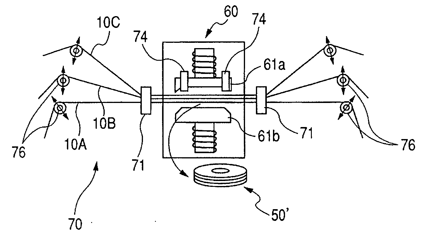
A method of manufacturing an optical recording medium is provided, which is capable of manufacturing a highly reliable optical recording medium, an eccentricity of each recording layer formed on each of a plurality of sheet-like substrates may be suppressed, and which does not involve a complicated process. Specifically, a plurality of sheet-like substrates are laminated by a laminating apparatus under the condition that a recording layer is formed on one surface of each of the plurality of sheet-like substrates, and an uncured adhesive layer is formed on the other surface thereof. The laminating apparatus performs centering of each sheet-like substrate before the process of curing the adhesive layers. Then, the adhesive layers are cured, and a punching apparatus punches the three-layered sheet-like substrates into a disk shape in a collective manner, thereafter.

Description

BACKGROUND OF THE INVENTION [0001] 1. Field of the Invention [0002] The present invention relates to an optical recording medium having a multi-layered structure in which a plurality of sheet-like substrates each having a recording layer are laminated, and to a method of manufacturing the optical recording medium. [0003] 2. Related Background Art [0004] Recently, an optical recording medium typified by an optical disk is being applied as a medium for recording various kinds of pieces of information in an audio visual field as well as a computer field. Further, as a result of spread of a mobile computer and advancement of diversification of information, there is a demand for a small optical recording medium with a large capacity. [0005] Information is recorded or reproduced with respect to the optical recording medium by using light. Uneven patterns (hereinafter, referred to as “signal pattern”) such as pits and pre-grooves for obtaining a tracking servo signal and the like are forme...

Claims


Application Information

Patent Timeline
IPC IPC(8): B32B37/00
CPCB32B37/1284B32B38/04Y10T156/1084B32B2038/1891B32B2429/02B32B38/185
Inventor YOKOYAMA, RYUICHIMORITA, KUNIYUKIKONISHI, MASAHITODEGUCHI, KYOSUKE
Owner CANON KK
Learn More