Valve-gated injection molding nozzle having an annular flow

a annular flow technology, which is applied in the field of valve gated injection molding nozzles, can solve the problems of poor cosmetic part quality, premature wear of pins and nozzles, and inability to adapt to certain valve gated hot runner nozzles

Active Publication Date: 2008-04-29
MOLD MASTERS 2007
View PDF51 Cites 14 Cited by
  • Summary
  • Abstract
  • Description
  • Claims
  • Application Information

AI Technical Summary

Problems solved by technology

One problem with valve pin gating is premature wear of the pin and the nozzle as a result of misalignment of the valve pin; this in turn may cause leakage and poor cosmetic part quality.
Certain known valve gated hot runner nozzles are not suitable when molding parts that require improved strength or higher esthetic merits.
This is because the valve pin behaves as an obstruction in the flow of the melt through the nozzle and towards the mold cavity.
The valve pin splits the melt flow and this creates undesirable flow lines that are visible or weakens the finished molded part.
Residue material from the first / subsequent color of the molten material conventionally causes numerous shots of injection molded products to be defective because they have an undesirable blend of two colors of molten material.
It is common for a substantial number of products to be defective in this way requiring multiple injection cycles to clear the runner system before useable products are formed.
Additionally or aside from when color change may be a problem, unidirectional molecular orientation and weld / flow lines can be a potential cause for weakness in the structural integrity, dimensional accuracy, or cause unwanted birefringence of molded products.

Method used


Image

  • Valve-gated injection molding nozzle having an annular flow
  • Valve-gated injection molding nozzle having an annular flow
  • Valve-gated injection molding nozzle having an annular flow

Examples


Embodiment Construction

Overview

[0024]While specific configurations and arrangements are discussed, it should be understood that this is done for illustrative purposes only. A person skilled in the pertinent art will recognize that other configurations and arrangements can be used without departing from the spirit and scope of the present invention. It will be apparent to a person skilled in the pertinent art that this invention can also be employed in a variety of other applications.

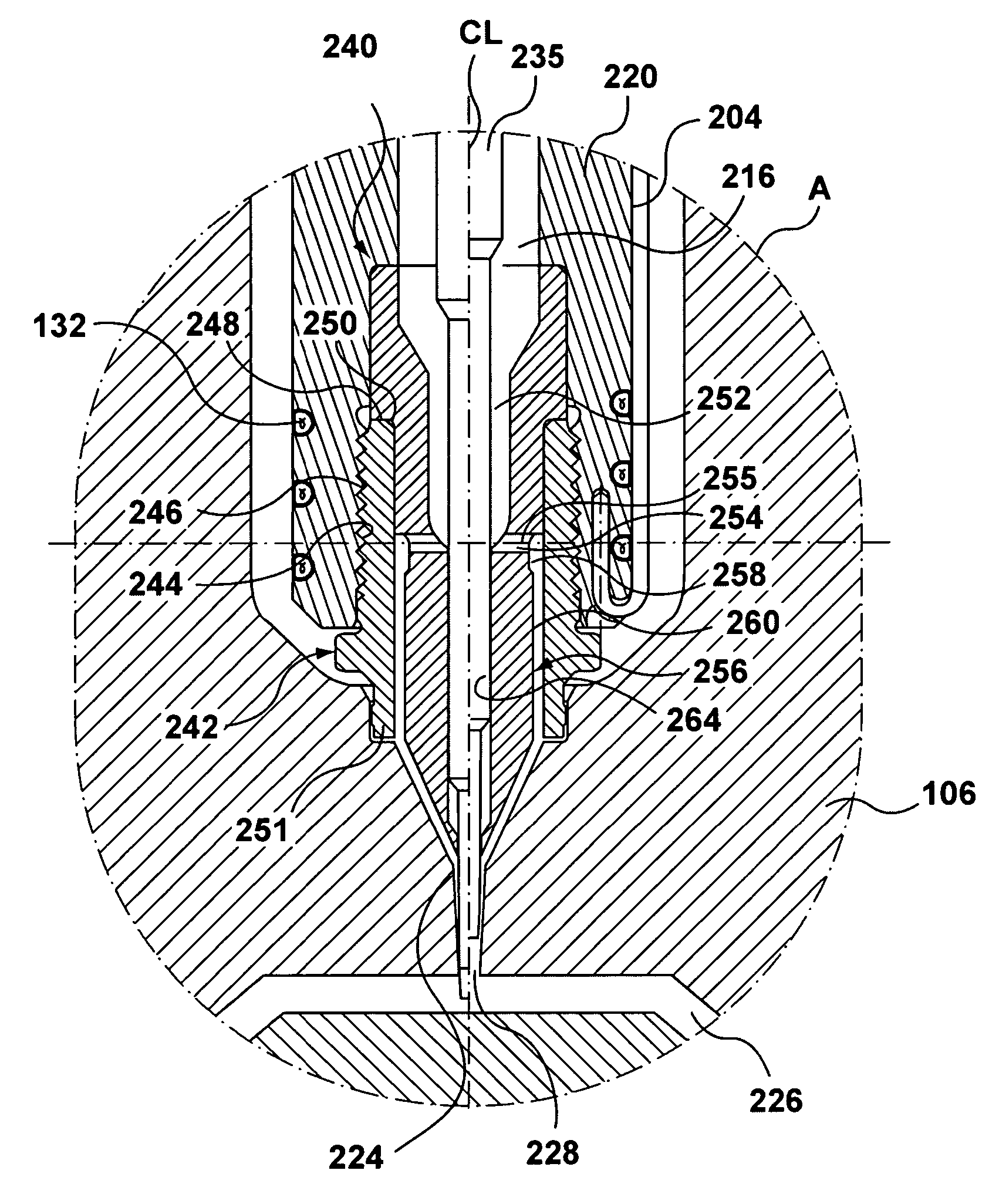
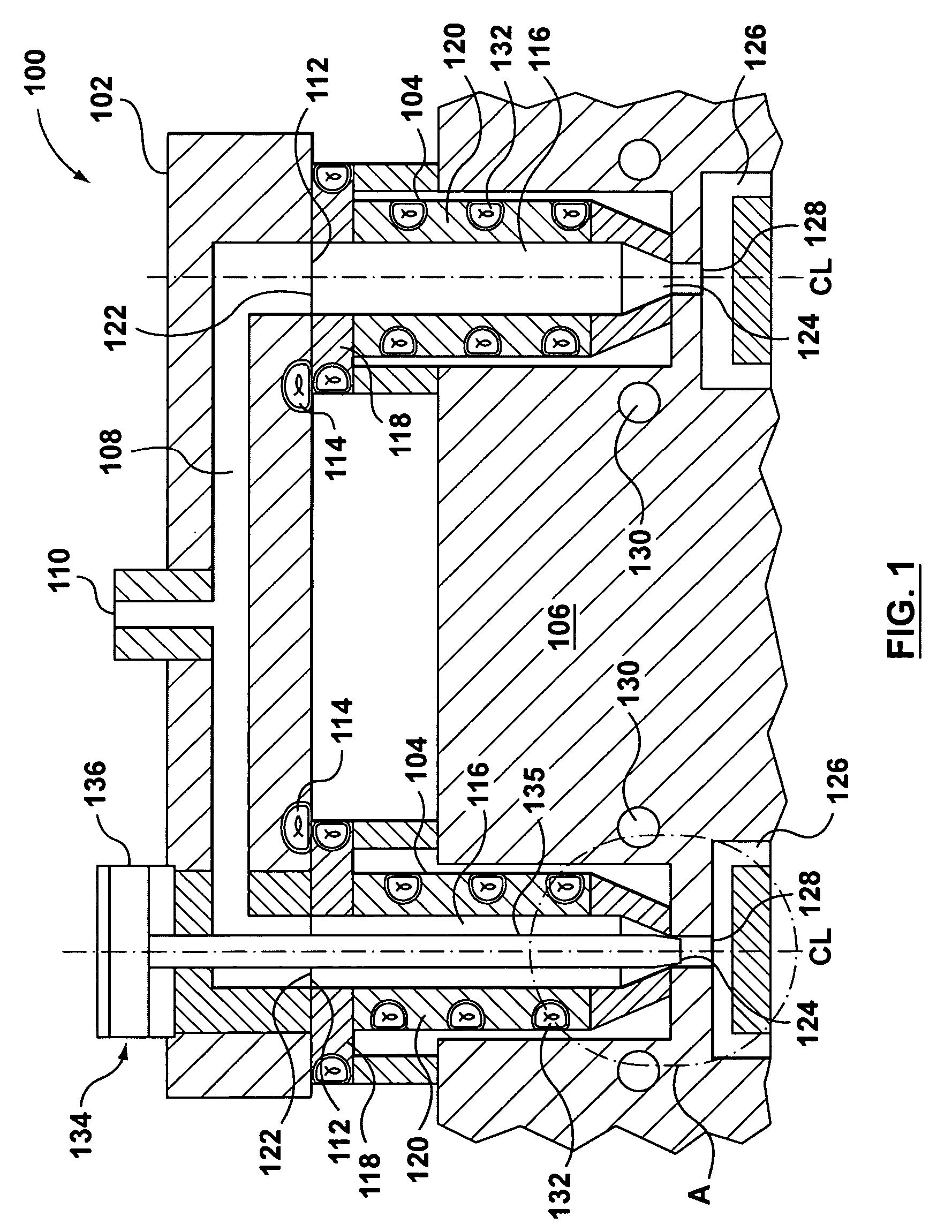
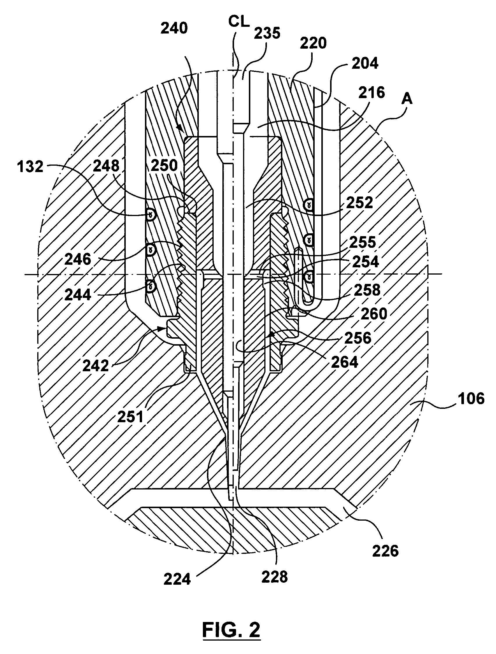
[0025]One or more embodiments of the present invention provide a valve-gated nozzle in an injection molding machine that allows for an improved flow of a molten material into a mold cavity, which can substantially reduce or eliminate flow lines in an injected molded product. In one example, this is accomplished through use of a valve-gated nozzle having a nozzle body with a nozzle melt channel in fluid communication with a nozzle tip, and which can also be in fluid communication with a manifold melt channel. The nozzle tip inc...


PUM

PropertyMeasurementUnit
angleaaaaaaaaaa
meltaaaaaaaaaa
areaaaaaaaaaaa

Abstract

A valve-gated nozzle in an injection molding machine allows for smooth, blended melt flow into a mold cavity. In one example, this is accomplished through use of a valve-gated nozzle having a nozzle body with a nozzle melt channel in fluid communication with a manifold melt channel and a nozzle tip. The nozzle tip includes a first melt channel in fluid communication with the nozzle melt channel and a plurality of release melt channels between the first melt channel and an annular melt channel. The annular melt channel is formed between a retaining device and the nozzle tip. The annular melt channel includes a decompression chamber in fluid communication with respective ones of the release melt channels and a compression chamber between the decompression chamber and a mold. A pressure difference formed between the respective release melt channels and the decompression chamber and between the decompression chamber and the compression chamber blends the molten material to even and balance flow into the mold cavity.

Description

CROSS REFERENCE TO RELATED APPLICATIONS[0001]This application claims benefit under 35 U.S.C. § 119(e) to U.S. Provisional Application No. 60 / 575,842, filed Jun. 2, 2004, which is incorporated by reference herein in its entirety.[0002]This application is related to co-pending U.S. application Ser. No. 11 / 065,167, filed Feb. 24, 2005, which claims benefit under 35 U.S.C. § 119(e) to U.S. Provisional Application No. 60 / 575,841, filed Jun. 2, 2004 which are incorporated by reference herein in their entireties.BACKGROUND[0003]1. Field of the Invention[0004]The present invention is related to a nozzle for an injection molding apparatus.[0005]2. Related Art[0006]Injection molding systems generally comprise an injection molding unit, an injection manifold and g one or more hot runner nozzles for receiving melt from a manifold and transferring / distributing the melt to one or more mold cavities. Hot runner systems offer the choice between thermal gating and valve gating. Valve gating is used ...

Claims


Application Information

Patent Timeline
Patent Type & Authority Patents(United States)
IPC IPC(8): B29C45/23B29C45/27B29C45/28B29C45/30
CPCB29C45/278B29C45/2806B29C45/30B29C2045/308
Inventor FAIRY, FABRICE
Owner MOLD MASTERS 2007
Why Eureka
Try Eureka