Method and equipment for producing polymer-film

a technology of polymer film and equipment, which is applied in the direction of dough extruders, dough shaping machines, manufacturing tools, etc., can solve the problems of uniform thickness of film, difficult to have a uniform thickness, and difficult to produce thereof, so as to reduce air-pressure fluctuation in the decompression chamber and the pipe to the decompression chamber, the effect of reducing the risk of affecting the production efficiency of the production process

Inactive Publication Date: 2005-03-24
FUJIFILM CORP
View PDF1 Cites 11 Cited by
  • Summary
  • Abstract
  • Description
  • Claims
  • Application Information

AI Technical Summary

Benefits of technology

[0015] According to the method of the present invention, the air-pressure fluctuation in the decompression chamber and the pipe to the decompression chamber can be reduced, and therefore the pressure change in the decompression chamber becomes smaller. Accordingly, the vibration of the discharged...

Problems solved by technology

However, when the film becomes thinner, the production thereof becomes harder, and especially it becomes extremely harder to have a uniform thickness.
The nonuniformity of the film thickness is a dea...

Method used


Image

  • Method and equipment for producing polymer-film
  • Method and equipment for producing polymer-film
  • Method and equipment for producing polymer-film

Examples


example 1

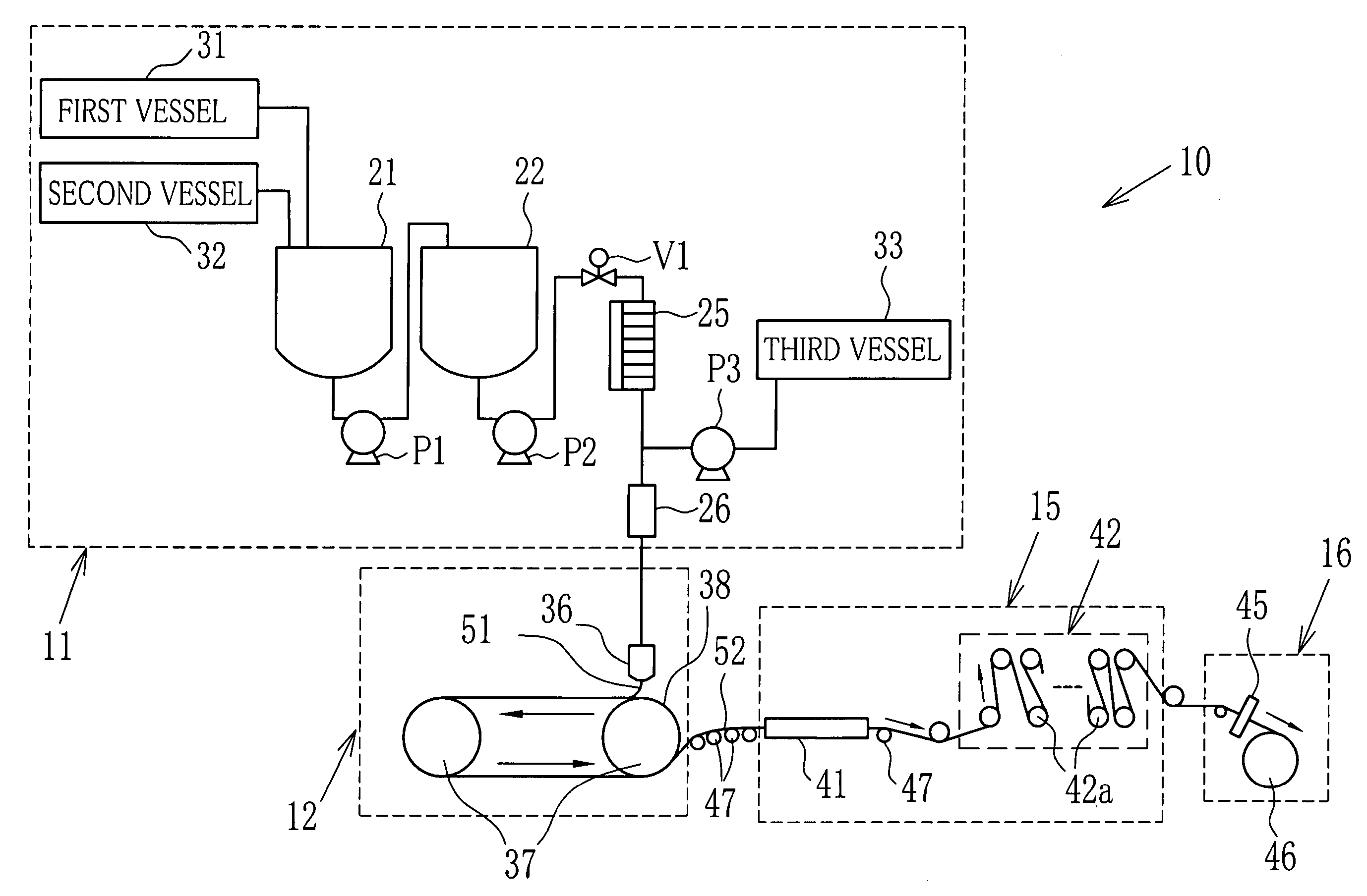
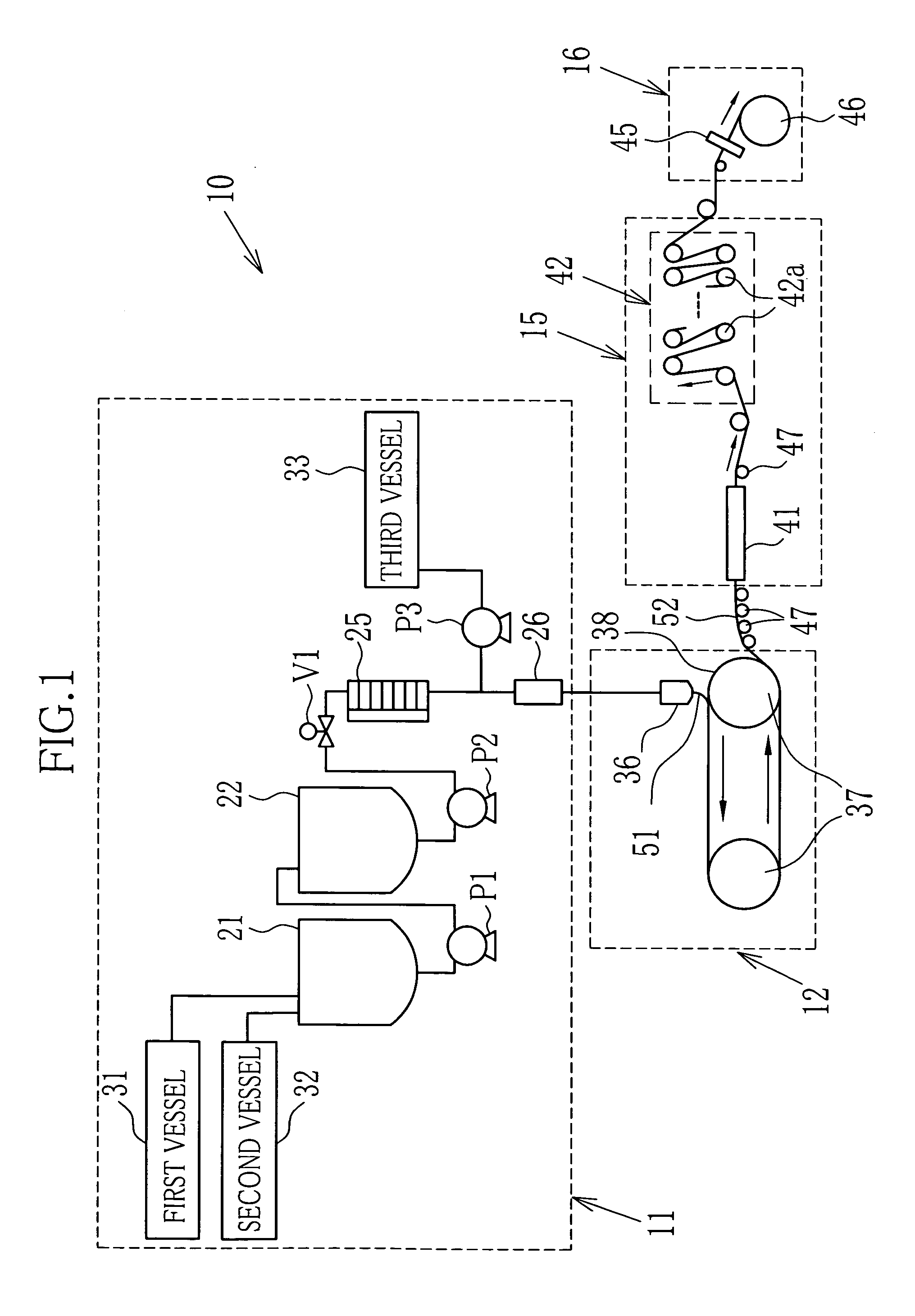
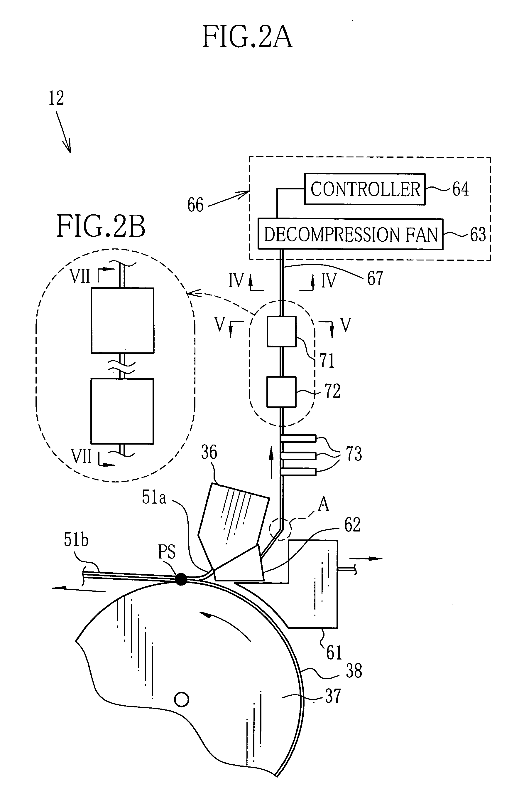
[0090] Solid contents in followings were added to a solvent as a mixture of dichloromethane and methanol in 92:8 of weight ratio. This mixture was stationary disposed to remove the bubbles, and thereafter fed to the filtering device 25 by the pump P2. Thus the dope 51 was obtained, and the solid density of the dope 51 was 19.0 wt. %. The dope 51 was cast from the casting die 36. The conveying speed of the belt 38 was 55 m / min. The reduction degree of the second decomposition chamber 62 was controlled during the performance of the casting. The inner diameter of the pipe 67 was 100 mm, and the length was 12 m. The number of the bend portion A was 8. Further, the first expansion silencer was the expansion type and the value S2 / S1 thereof was 50. The first expansion silencer 71 and the second expansion silencer 72 have no sectioning members, and have the length L1 of 3.5 m and the length L2 of 2.5 m, respectively. Further, as the fluctuation suppressing device, the resonance silencer 73...

example 2

[0093] The thickness of the produced film 52 was 60 μm, and other conditions were the same as Example 1. Thus three films of Examples 2-A, 2-B, 2-C were produced. The results are shown in Table 1.

example 3

[0094] The thickness of the produced film 52 was 40 μm, and other conditions were the same as Example 1. Thus three films of Examples 3-A, 3-B & 3-C were produced. The results are shown in Table 1.

TABLE 1PredeterminedDecompression DegreeThickness|PV|Example(Pa)Unevenness(−)1-A−1001.40N1.20B0.80B0.40A1-B−3002.40N1.90B1.40B0.60A1-C−5003.10N2.80B2.20B0.80A2-A−1001.20N0.90B0.70B0.30A2-B−3002.10N1.40B0.60B0.30A2-C−5002.70N2.30B1.60B0.80A3-A−1001.00N0.80B0.60B0.30A3-B−3001.70N1.40B1.00B0.40A3-C−5002.20N1.80B1.30B0.50A

[0095] According to Table 1, when Pv was at least 1.5|K| (herein |K|=(t×|P0|)1 / 2100) the thickness unevenness was almost not observed and the quality of the obtained film was high. When |Pv| was at most 0.5|K|, the thickness unevenness not observed and the quality of the obtained film was quite high.


PUM

PropertyMeasurementUnit
Lengthaaaaaaaaaa
Lengthaaaaaaaaaa
Lengthaaaaaaaaaa

Abstract

A dope is discharged from a casting die toward a belt to form a film-like material above the belt. Thereby a range near the film-like materials is decompressed by first and second decompression chambers. A pipe connecting each decompression chamber to a pressure controller has an inner diameter from 70 mm to 700 mm, and a length of the pipe is at most 30 m. Further the pipe is provided with a first expansion silencer of expansion silencer and a second expansion silencer of resonance silencer, and a sectional dimension ratio of the first expansion silencer to the pipe is from 5 to 500. Thus a pressure fluctuation in the second decompression chamber and the pipe is reduced and the film-like material becomes uniform. Thus the obtained film has no thickness unevenness, and used for producing a polarizing filter excellent in optical properties and a liquid crystal display.

Description

BACKGROUND OF THE INVENTION [0001] 1. Field of the Invention [0002] The present invention relates to a method and an equipment for producing a film, especially a method and an equipment for producing a film for an optical use. [0003] 2. Description Related to the Prior Art [0004] In an optoelectronics field are used many polymer films which are produced in a solution casting method. The polymer film produced in the solution casting method is more excellent in an optical isotropy and a uniform thickness, and contains foreign materials less than a film produced in a melt-extrusion method. Therefore the polymer film is used, for example, as a protective film for a polarizing filter, a retardation film, a transparent conductive film, and the like. Especially among such polymer films, a cellulose acylate film is widely used since having transparency and adequate moisture permeability, high mechanical strength, and low dependency of a size stability on humidity and temperature. In the sol...

Claims


Application Information

Patent Timeline
IPC IPC(8): B29C41/28B29C41/30B29C41/50B29C41/52
CPCB29C41/28B29C41/30B29C41/50B29C41/52
Inventor KANEMURA, KAZUHIDE
Owner FUJIFILM CORP
Why Eureka
Try Eureka