Stator for an electrical machine

a technology of electrical machines and stators, applied in the field of stators, can solve the problems of saving a large amount of time and money, and achieve the effect of simplifying the wiring arrangement of the stator

Active Publication Date: 2008-04-29
ZF FRIEDRICHSHAFEN AG
View PDF11 Cites 5 Cited by
  • Summary
  • Abstract
  • Description
  • Claims
  • Application Information

AI Technical Summary

Benefits of technology

[0007]An object of the present invention is to simplify the wiring arrangement of the stator, in particular so that the individual processes involved in connecting the wiring can be accomplished reliably and can be performed by automated equipment.
[0008]According to the invention, the contact areas of the ends of the coils are arranged in a common axial and radial position with the wiring arrangement. As a result, the contacting can be carried out automatically by a stationary tool while the stator is supported with freedom to rotate around a center axis, without the need for any additional radial feed movements. A considerable increase in productivity can be achieved when the end of one coil and the circumferentially adjacent end of a second coil are assigned to one and the same linking conductor by means of a common terminal element. This means that, per joining operation, two coil ends are connected simultaneously, as a result of which a considerable amount of time and money is saved in the production of a stator.

Problems solved by technology

This means that, per joining operation, two coil ends are connected simultaneously, as a result of which a considerable amount of time and money is saved in the production of a stator.

Method used


Image

  • Stator for an electrical machine
  • Stator for an electrical machine
  • Stator for an electrical machine

Examples


Embodiment Construction

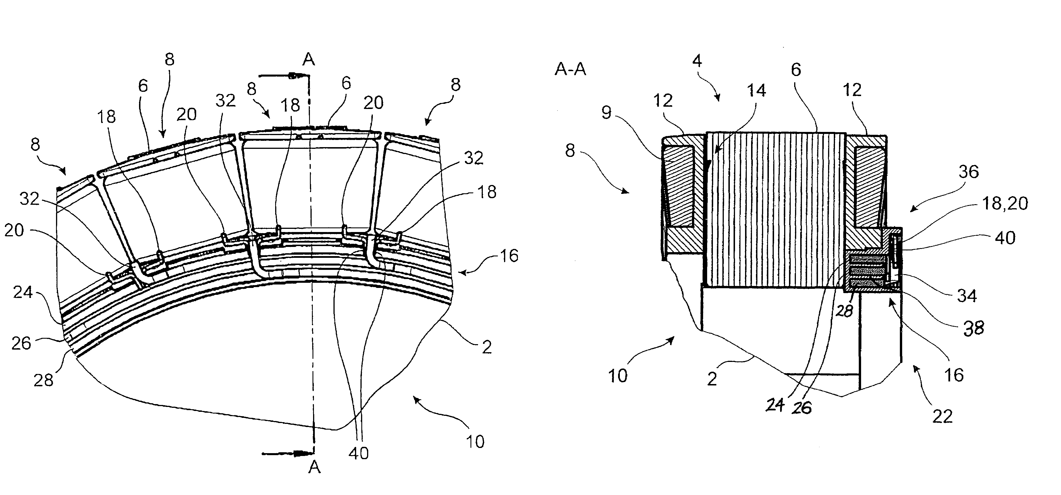
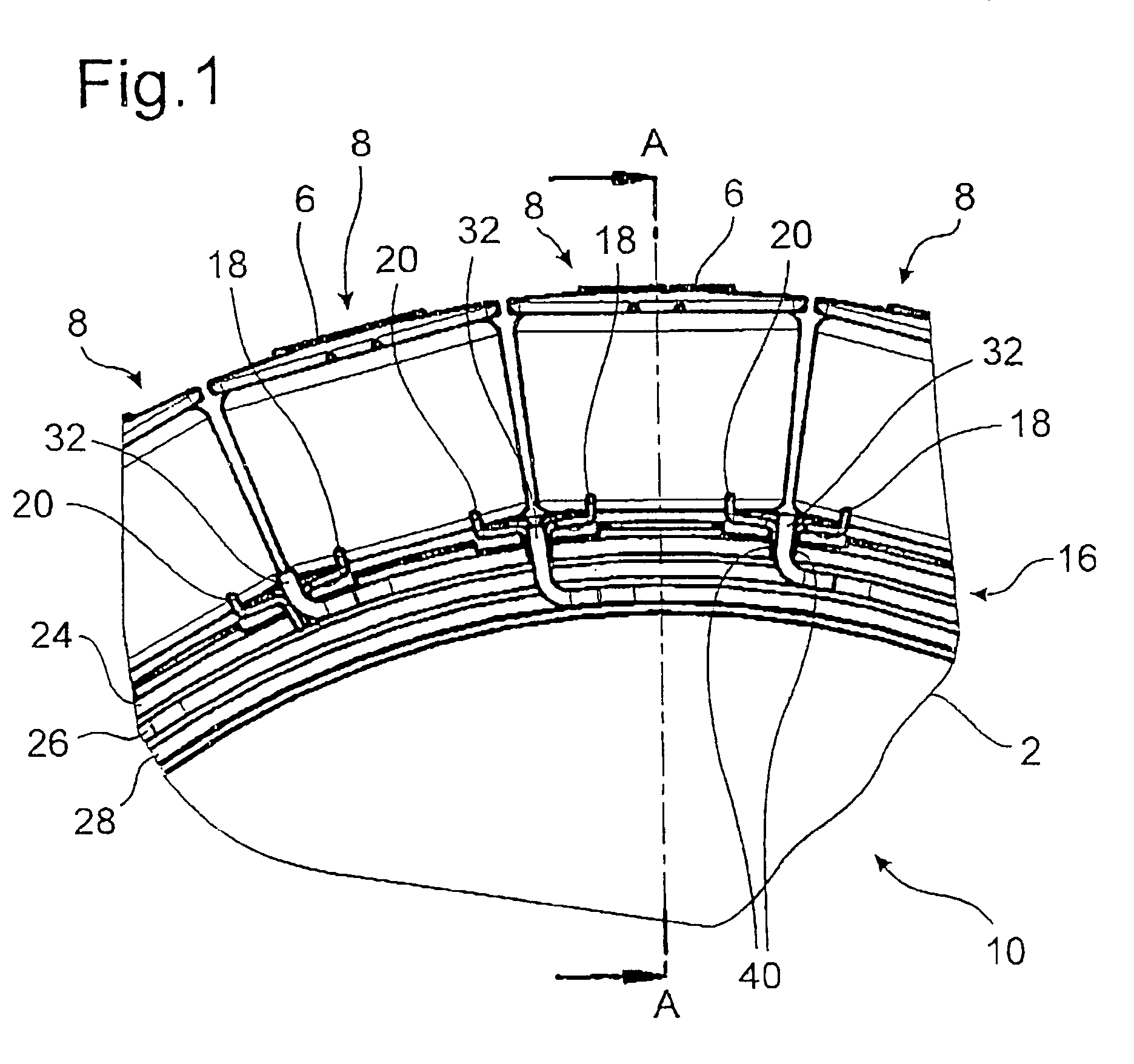
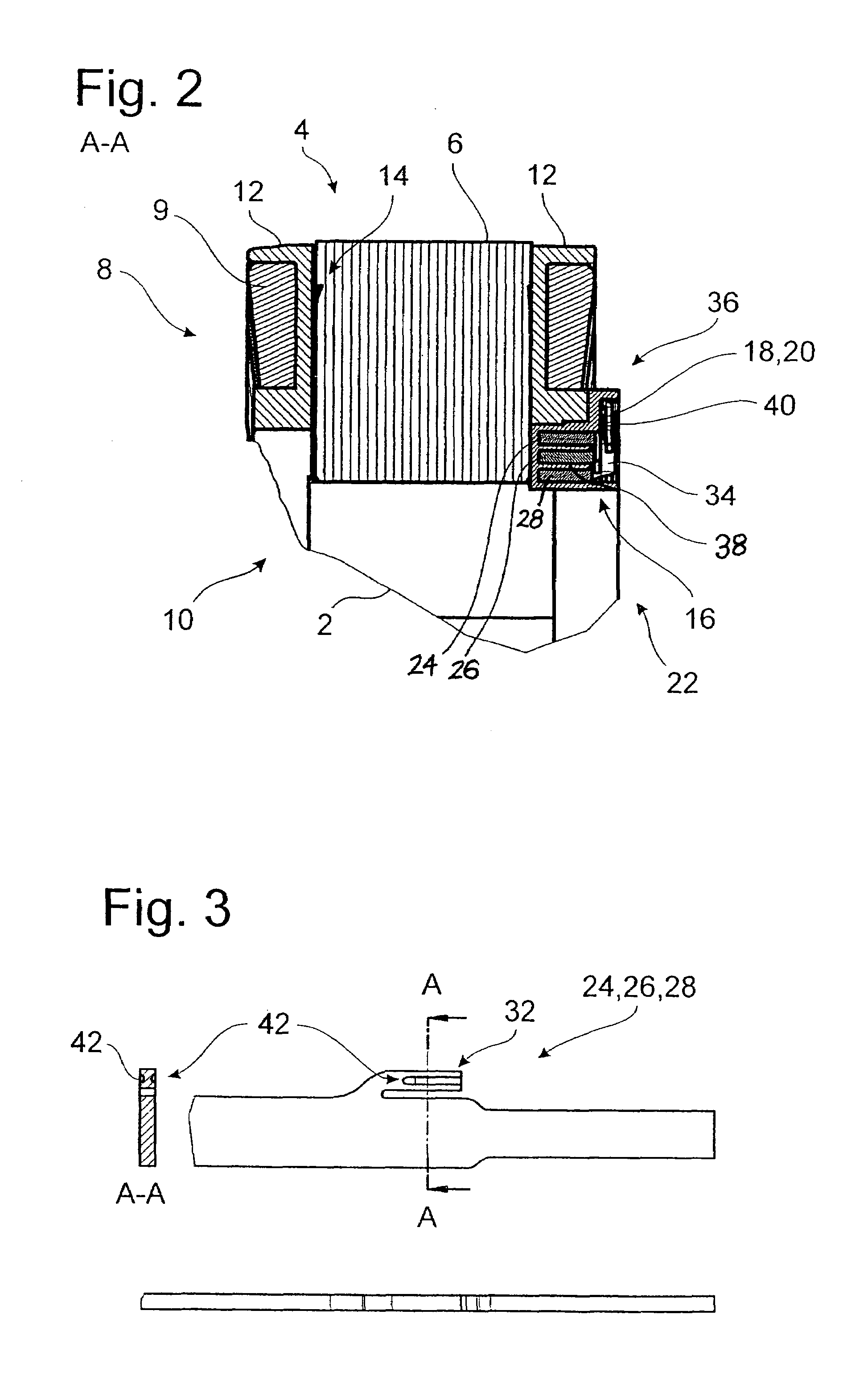
[0019]FIGS. 1-4 show a first exemplary embodiment, and FIGS. 5-9 show a second embodiment of a stator 10 with a wiring arrangement 16′. The design of the stator winding is identical in both cases. The only differences pertain to the design of the wiring arrangement.

[0020]FIGS. 1 and 2 show part of a stator 10, mounted on a cooled hub 2, for an electrical machine (not shown). The stator has a ring-shaped stator yoke 4 consisting of laminations of electrical steel. This is the stator of a synchronous electrical machine of the external rotor type excited by permanent magnets. The special design of the electrical machine is irrelevant to the following explanation, however; the machine could be, for example, an induction motor, a reluctance machine of the internal, external, or disk rotor type, or any other type of electrical machine. The stator yoke 4 has a number of radially outward-oriented teeth 6 arranged around the circumference. Each tooth 6 carries an individual coil 8. The coils...


PUM


Abstract

In a plurality of stator coils arranged on the yoke, each coil has a pair of ends, each end being adjacent to a respective end of an adjacent coil to form pairs of adjacent ends. A plurality of mutually insulated concentrically arranged linking conductors each has a plurality of circumferentially arranged terminal elements, each terminal element being electrically connected to a respective pair of adjacent ends to form a contact area in a common axial and radial position.

Description

BACKGROUND OF THE INVENTION[0001]1. Field of the Invention[0002]The invention pertains to a stator having a yoke, a plurality of stator coils arranged on the yoke, and a plurality of mutually insulated linking conductors having terminal elements connected to ends of the stator coils.[0003]2. Description of the Related Art[0004]Known stators for electrical machines have a stator yoke with a number of stator teeth, which carry the electrical winding in the form of, for example, individually wound stator coils of insulated wire. The two ends of each coil are assigned to individual strands and are connected to each other in a predetermined manner by common linking conductors. In the case of a three phase machine, the stator has three strands and thus at least three linking conductors, each of which is supplied with current with a phase offset of 120°. The linking conductors are wired to a switch box so that the electrical machine can be connected to a power source.[0005]U.S. Pat. No. 6,...

Claims


Application Information

Patent Timeline
Patent Type & Authority Patents(United States)
IPC IPC(8): H02K11/00
CPCH02K3/38H02K3/522H02K15/0056
Inventor HERLET, WERNERBUTTNER, HUBERTUSFISTER, MICHAELSCHMITT, BERNHARDVAN HEYDEN, MARCUSVOLLMUTH, ALFONSRODER, MANFREDJAFOUI, KHALIDBAUMEISTER, JENSWELKE, KNUT
Owner ZF FRIEDRICHSHAFEN AG
Why Eureka
Try Eureka