Disk drive comprising an optical sensor for vibration mode compensation

a technology of optical position sensor and optical drive, which is applied in the direction of undeired vibration/sound insulation/absorption, instruments, data recording, etc., can solve the problems of poor disturbance rejection, excessive settling time, poor tracking

Inactive Publication Date: 2008-04-29
WESTERN DIGITAL TECH INC
View PDF66 Cites 119 Cited by
  • Summary
  • Abstract
  • Description
  • Claims
  • Application Information

AI Technical Summary

Benefits of technology

[0010]In another embodiment of the present invention, the optical sensor comprises a light source, a plurality of light sensitive sensors positioned to receive light from the light source, and a substantially opaque element positioned between the light source and the light sensitive sensors configured to control an amount of light at least one of the plurality of light sensitive sensors detects relative to the position of the actuator arm. In one embodiment, the opaque element is coupled to a side of the actuator arm proximate the pivot. In another embodiment, the plurality of light sensitive sensors comprise a first sensor and a second sensor, and the optical sensor further comprises a differential amplifier operable to compute a difference between a first amount of light detected by the first sensor and a second amount of light detected by the second sensor, wherein the difference represents the position of the actuator arm. In yet another embodiment, the plurality of light sensitive sensors comprise a first sensor and a second sensor, the optical sensor further comprises a differential amplifier operable to compute a sum of the first amount of light detected by the first sensor and the second amount of light detected by the second sensor, and an intensity of the light is controlled in response to the sum.
[0011]In still another embodiment, the control signal applied to the voice coil motor is generated in response to a difference between the first and second position signals.
[0012

Problems solved by technology

Seeking and tracking operations can excite vibration modes of the actuator arm assembly and VCM that may interfere with the frequency response of the servo system.
In p

Method used


Image

  • Disk drive comprising an optical sensor for vibration mode compensation
  • Disk drive comprising an optical sensor for vibration mode compensation
  • Disk drive comprising an optical sensor for vibration mode compensation

Examples


Embodiment Construction

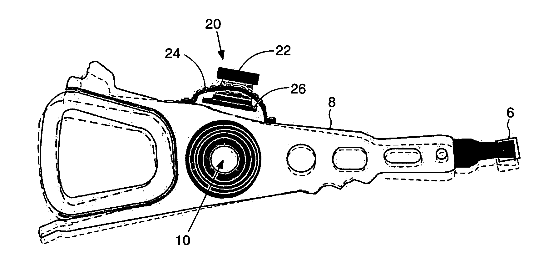
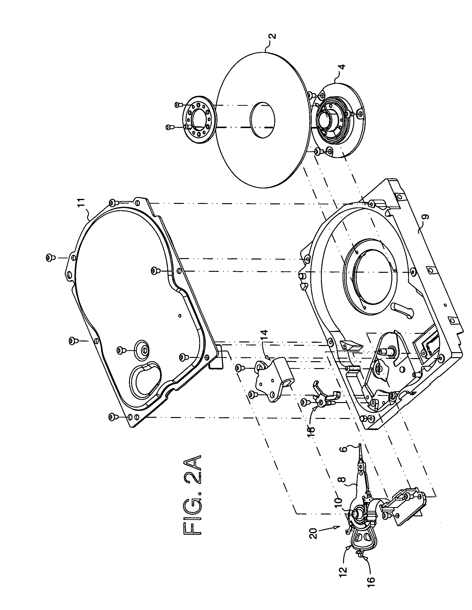
[0033]FIG. 2A shows a disk drive according to an embodiment of the present invention comprising a disk 2 having a plurality of servo sectors 210-21N (FIG. 2B) comprising servo information, wherein the servo sectors 210-21N define a plurality of servo tracks 23. The disk drive further comprises an actuator arm 8, a head 6 attached to a distal end of the actuator arm 8, a voice coil motor for rotating the actuator arm 8 about a pivot 10, and an optical sensor 20 operable to generate a first position signal representing a position of the actuator arm 8 with respect to the disk 2, wherein the first position signal is substantially unaffected by a vibration mode of the actuator arm 8. Control circuitry within the disk drive processes the servo information to generate a second position signal representing a position of the head 6 with respect to the disk 2, wherein the second position signal comprises a significant component due to the vibration mode of the actuator arm 8. The control cir...


PUM


Abstract

A disk drive is disclosed comprising an actuator arm, a head attached to a distal end of the actuator arm, a voice coil motor for rotating the actuator arm about a pivot, and an optical sensor operable to generate a first position signal representing a position of the actuator arm with respect to the disk, wherein the first position signal is substantially unaffected by a vibration mode of the actuator arm. Servo sectors recorded on the disk are processed to generate a second position signal representing a position of the head with respect to the disk, wherein the second position signal comprises a significant component due to the vibration mode of the actuator arm. A control signal is applied to the voice coil motor in response to the first and second position signals.

Description

BACKGROUND OF THE INVENTION[0001]1. Field of the Invention[0002]The present invention relates to disk drives for computer systems. More particularly, the present invention relates to a disk drive comprising an optical position sensor for vibration mode compensation.[0003]2. Description of the Prior Art[0004]FIG. 1 shows an exploded view of a prior art disk drive comprising a disk 2 rotated by a spindle motor 4, and a head 6 coupled to a distal end of an actuator arm 8 which is rotated about a pivot 10 by a voice coil motor (VCM) in order to actuate the head 6 over the disk 2. The disk 2, spindle motor 4, head 6, actuator arm 8, and VCM are enclosed in a head disk assembly (HDA) comprising a base 9 and a cover 11. The VCM comprises a voice coil 12 coupled to the base of the actuator arm 8 and one or more permanent magnets attached to a yoke 14. When the voice coil 12 is energized with current, the resulting magnetic flux interacts with the magnetic flux of the permanent magnets to ge...

Claims


Application Information

Patent Timeline
IPC IPC(8): G11B5/596G11B5/55G11B15/18
CPCG11B5/5569G11B5/5582G11B5/59677G11B33/08
Inventor BENNETT, GEORGE J.
Owner WESTERN DIGITAL TECH INC
Why Eureka
Try Eureka