Fringing field focus motor and mechanism for optical disk drive

Inactive Publication Date: 2005-11-29
DPHI ACQUISITIONS +1
View PDF3 Cites 4 Cited by
  • Summary
  • Abstract
  • Description
  • Claims
  • Application Information

AI Technical Summary

Benefits of technology

[0015]The fringing field focus motor (FFFM) has several advantages over prior designs. The first is improved bandwidth. For purposes of this invention, “bandwidth” refers to the useful frequency ranges in which the electromechanical servo systems of the arm can maintain (the required) focus and tracking accuracy. Because the focus mechanism is carried on the tracking arm, the focus servo system affects the tracking servo system. The high bandwidth and low mass of the focus mechanism components located on the tracking arm result in a tracking arm of lower mass, which minimizes lessens the moment about the axis. Thus the highly efficient and lightweight focus mechanism results in increased bandwidth of the tracking arm servo system as well as enabling a single stage actuator arm capable of both high bandwidth focus and tracking servo systems. An actuator incorporating the FFFM can maintain focus and tracking over a wide range of media imperfections or disturbances occurring over a wide range of frequencies. The fringing field passing through the coil substantially parallel to the surface of the disk results in a larger focusing component of force (in the Z direction) and thus creates not only a more efficient motor, but also allows placement of the FFFM focus coil substantially parallel to the surface of the disk and thus improves both the structure and balance of the arm. Improved structure and balance both allow broader effective focus bandwidth for an actuator incorporating the FFFM. Prior designs utilized more complicated two stage designs to minimize mass of one portion of the actuator and thereby increase total system bandwidth. The more efficient and lower mass FFFM allows a simpler, lower cost single stage rotary actuator arm. The second advantage is decreas

Problems solved by technology

Prior designs utilized more complicated two stage designs to minimize mass of one portion of the actuator and thereby increase total system bandwidth.
Prio

Method used


Image

  • Fringing field focus motor and mechanism for optical disk drive
  • Fringing field focus motor and mechanism for optical disk drive
  • Fringing field focus motor and mechanism for optical disk drive

Examples


Embodiment Construction

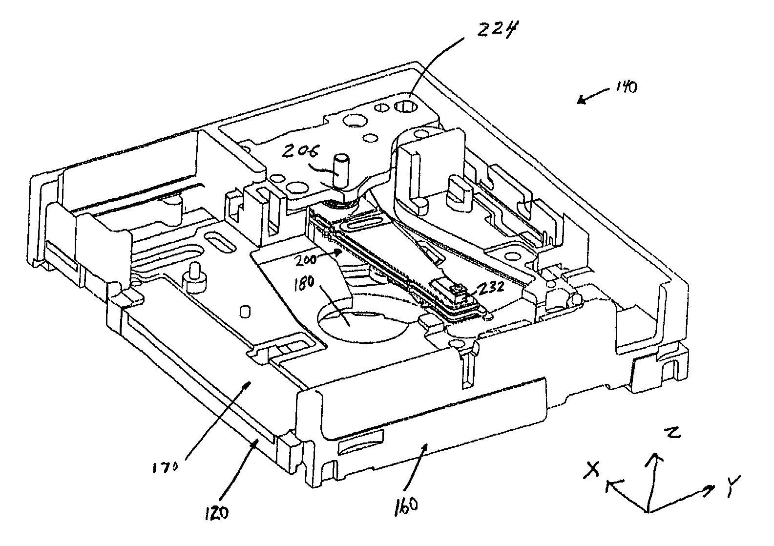
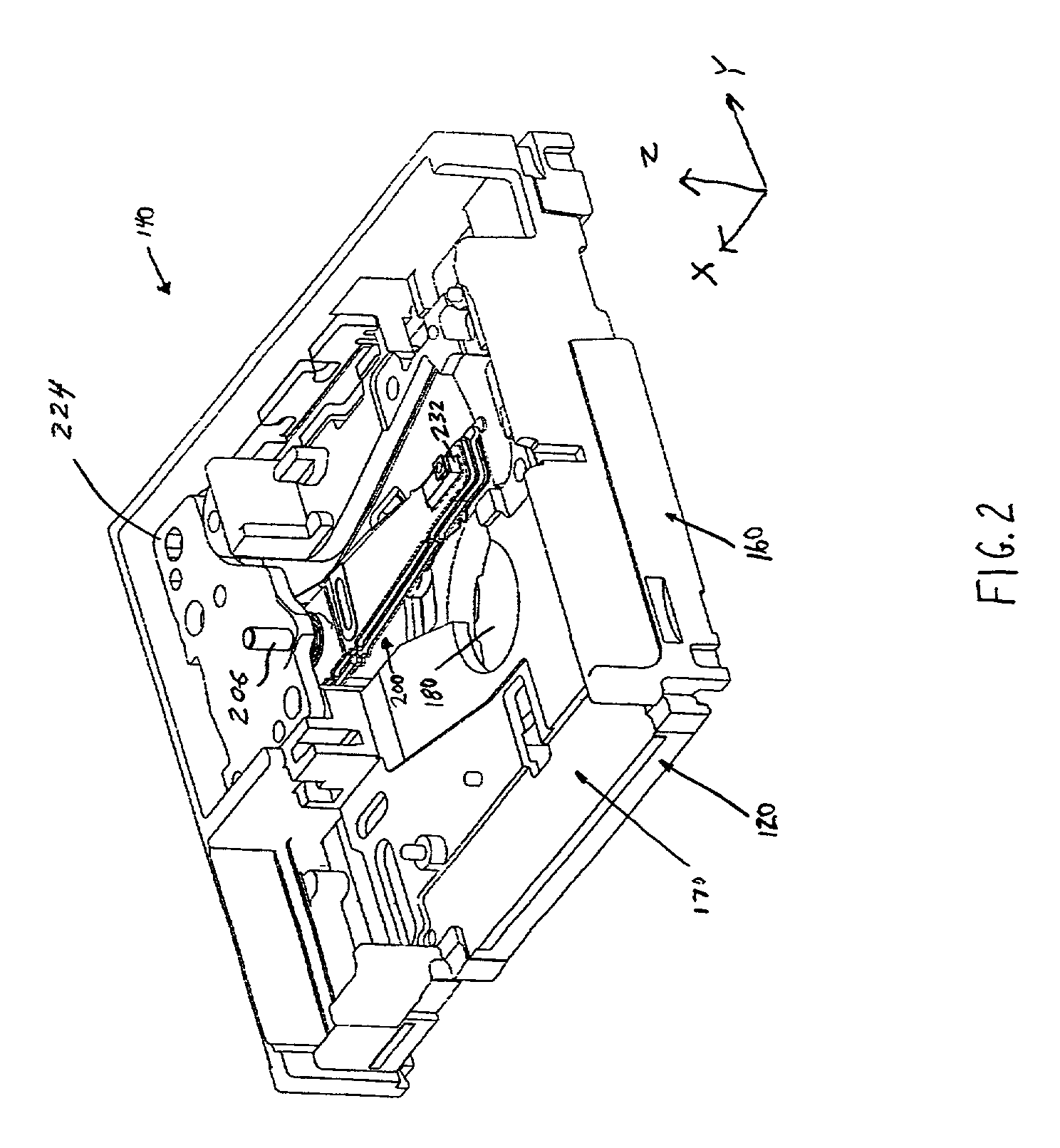
[0029]Turning to FIG. 2, a first embodiment of an actuator arm 200 is shown within the housing 120 of an optical drive 140. The housing 120 includes a base plate 160 having an aperture 180 for receiving a spin motor (not shown) and a slot 170 to receive a cartridge containing an optical disk (not shown). A cartridge is inserted into the slot 170 and engages the spin motor. An optical pick up unit (OPU) 232 is positioned at the distal end of the actuator arm 200 and directs a light beam (not shown), such as a laser, to an optical disk within the cartridge which is spinning at a rapid rate. The light beam may be used to write information to the disk or may be used to read information resident on the disk. Because information is stored on the disk in tracks, typically spirally or concentrically arranged, the OPU 232 must be able to traverse the surface of the disk from the inside to the outside diameter in order to access the information formatted on the disk. To accomplish this, actua...


PUM


Abstract

A system for controlling a distance between an optical head and the surface of a rotating optical disk comprising: an actuator arm having a first and second surface, the first surface facing the optical disk, the second surface facing away from the optical disk; an electromagnetic coil having an inner void, said coil adjacent to the second surface of the arm; and at least one permanent magnet producing a magnetic field that passes through the coil such that when an electric current is applied to the coil, a force is created at two or more segments of the coil.

Description

CROSS-REFERENCE TO RELATED APPLICATIONS[0001]The present application is related to patent application Ser. No. 09 / 560,781, filed Apr. 28, 2000, entitled “Miniature Optical Disk for Data Storage,” patent application Ser. No. 09 / 548,128, filed Apr. 12, 2000, entitled “Low Profile and Medium Protecting Cartridge Assembly,” patent application Ser. No. 09 / 540,657, filed Mar. 31, 2000, entitled “Low Profile Optical Head,” patent application Ser. No. 09 / 393,899, filed Sep. 10, 1999, entitled “Content Distribution Method and Apparatus,” patent application Ser. No. 09 / 393,150, filed Sep. 10, 1999, entitled “Writeable Medium Access Control Using a Medium Writeable Area,” Provisional Application Ser. No. 60 / 140,633, filed Jun. 23, 1999, entitled “Combination Mastered and Writeable Medium and Use in Electronic Book Internet Appliance,” and patent application Ser. No. 09 / 315,398, filed May 20, 1999, entitled “Removable Optical Storage Device and System,” all of which are incorporated herein by r...

Claims


Application Information

Patent Timeline
IPC IPC(8): G07F7/00G07F7/02G07F17/16G11B7/085G11B7/09G11B21/20
CPCG06Q20/3433G07F7/02G07F17/0014G07F17/16G11B7/0908G11B7/0927G11B21/20G11B7/08576G11B20/0071
Inventor RAYMOND, PETER J.BERG, THOMAS E.
Owner DPHI ACQUISITIONS
Why Eureka
Try Eureka