Cooling system and method

a cooling system and cooling method technology, applied in ventilation systems, electrical apparatus casings/cabinets/drawers, domestic cooling apparatus, etc., can solve problems such as increasing the number of electrical devices mounted in each rack, raising concerns about adequate cooling of equipment, and heat produced by rack-mounted equipment that can have adverse effects on the performance, reliability and useful life of equipment components

Active Publication Date: 2008-04-29
SCHNEIDER ELECTRIC IT CORP
View PDF81 Cites 187 Cited by
  • Summary
  • Abstract
  • Description
  • Claims
  • Application Information

AI Technical Summary

Benefits of technology

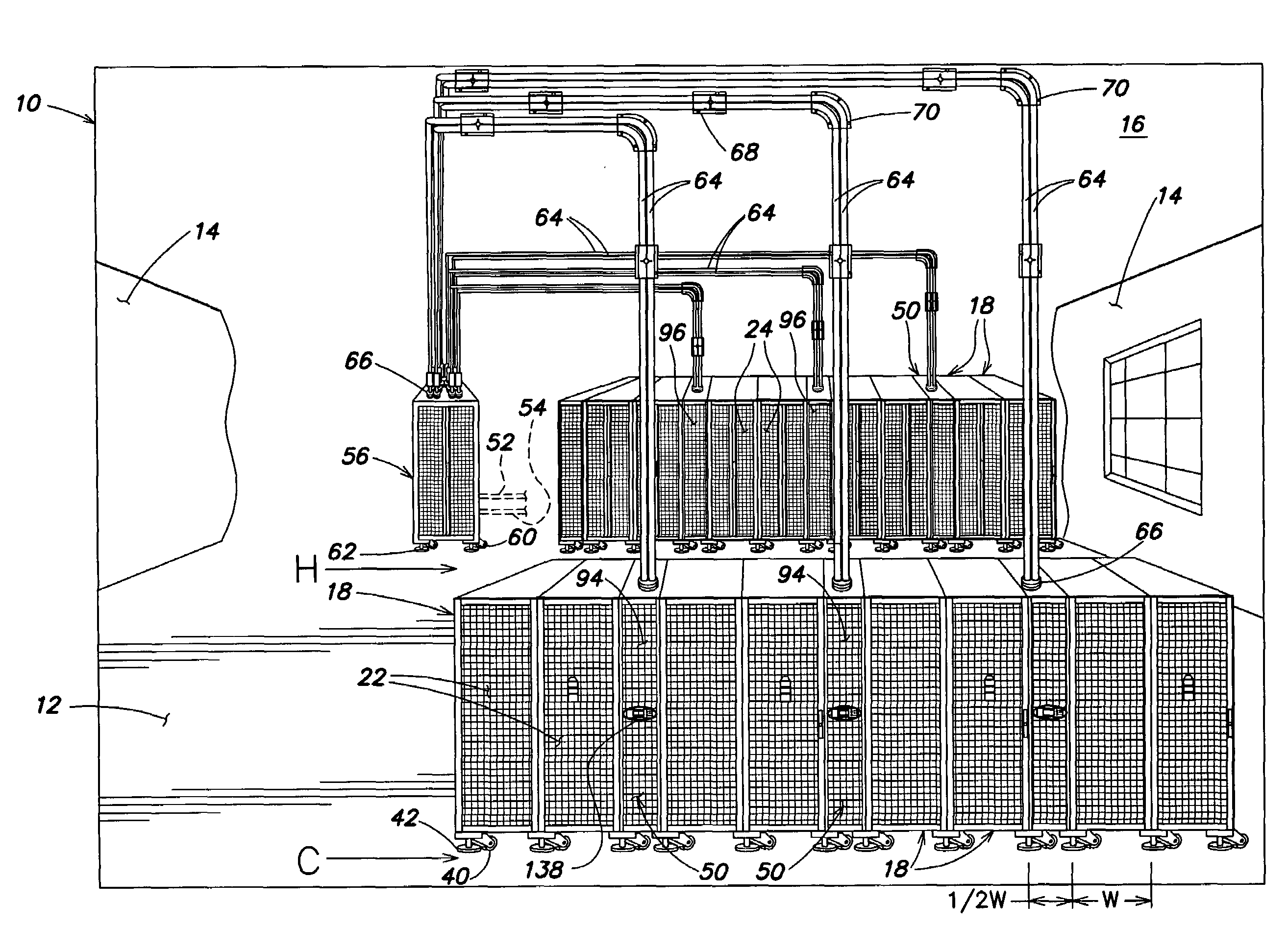
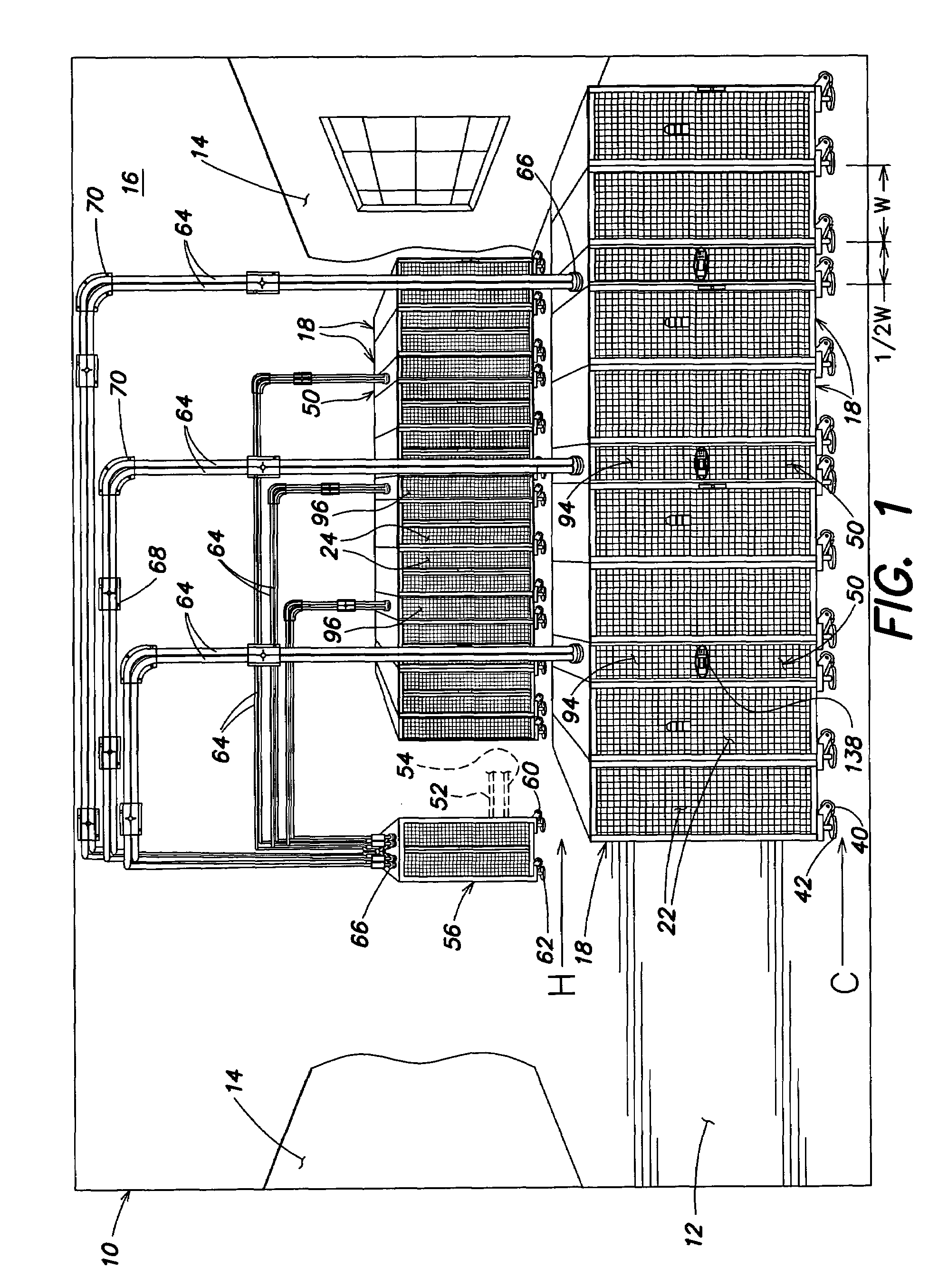
[0103]One further benefit to the cooling system of embodiments of the present invention is that during the planning of the original design, the flexible tubing may be planned for all current and future requirements, even if the future requirements for cooling equipment is not installed. For example, the future plan may be based on a worse case (i.e., maximum) cooling requirement. The distribution box and some overhead flexible tubing, support members and clamps may be made in the future design, even if no cooling racks are installed at that particular time. In such a system, provision is made for filling this tubing with water and removing all air from the tubing without shutting down the distribution box, which is already supplying the existing cooling racks with coolant. In this way, additional cooling racks may be added in the future without shutting down the cooling system.

Problems solved by technology

Further, with the ever decreasing size of computer equipment, and in particular, computer servers and blades, the number of electrical devices mounted in each rack has been increasing, raising concerns about adequately cooling the equipment.
Heat produced by rack-mounted equipment can have adverse effects on the performance, reliability and useful life of the equipment components.
In particular, rack-mounted equipment, housed within an enclosure, may be vulnerable to heat build-up and hot spots produced within the confines of the enclosure during operation.
A disadvantage of the CRAC-type air conditioning system is that cool air is mixed with the room temperature air, which is inefficient.
For large data centers requiring CRAC units at or near the middle or center of the data center room, delivery of coolant to the CRAC units must be located within the raised floor since it is undesirable to secure coolant piping to the ceiling of the data center due to risks involved with the possible failure of the piping joints.
Specifically, with traditional CRAC systems, the piping of the units requires significant cutting and hand soldering of pipes.
Leaks are common and leaking water or coolant in a data center may result in risk of damage to equipment housed within the equipment racks.
In addition, the potential of earthquakes may shake the pipes and cause the joints to fail.
For at least these reasons, most data center designers and operators are unwilling to consider overhead piping for cooling a data center.

Method used


Image

  • Cooling system and method
  • Cooling system and method
  • Cooling system and method

Examples


Embodiment Construction

[0049]This invention is not limited in its application to the details of construction and the arrangement of components set forth in the following description or illustrated in the drawings. The invention is capable of other embodiments and of being practiced or of being carried out in various ways. Also, the phraseology and terminology used herein is for the purpose of description and should not be regarded as limiting. The use of “including,”“comprising,”“having,”“containing”, “involving”, and variations thereof herein, is meant to encompass the items listed thereafter and equivalents thereof as well as additional items.

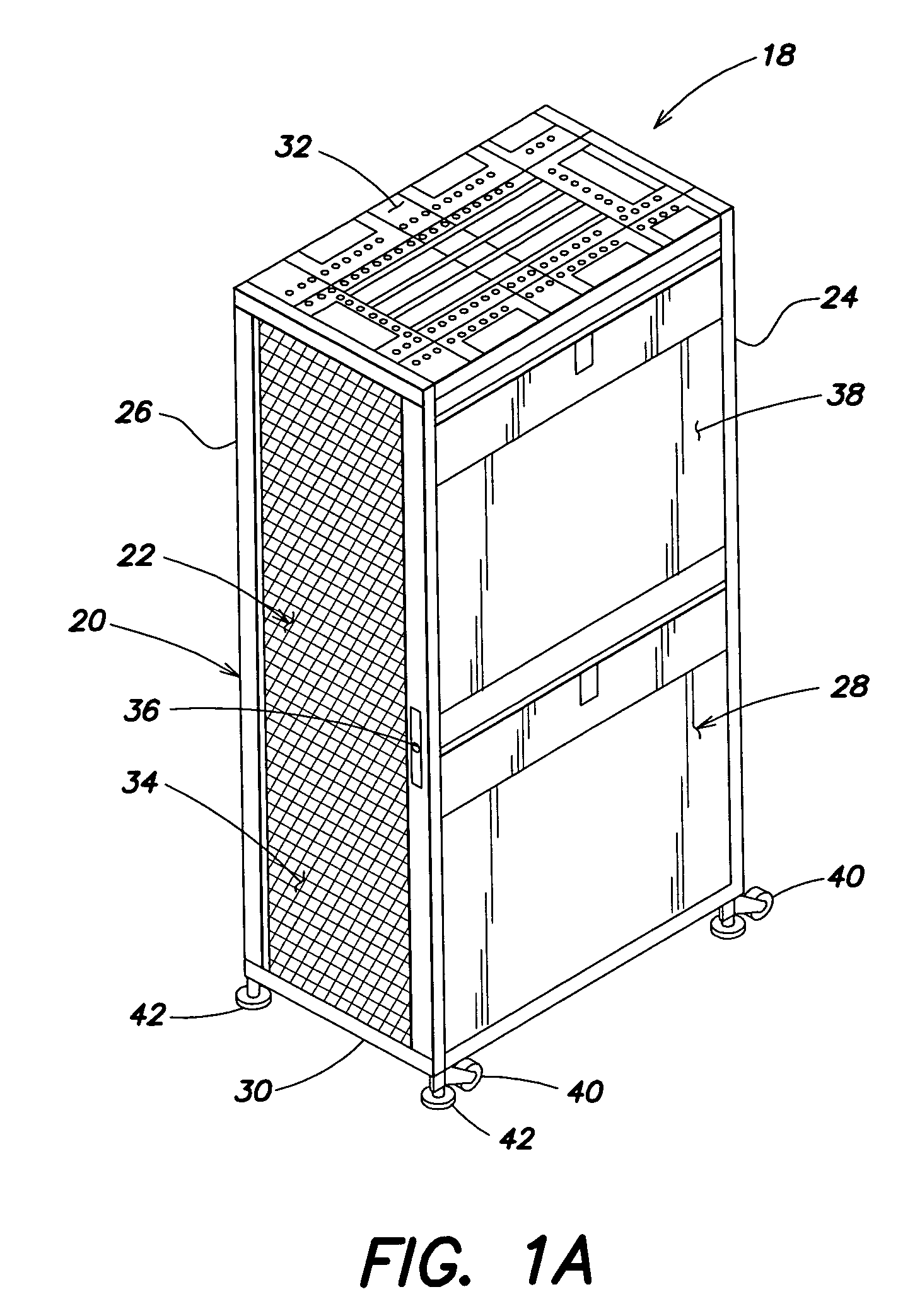
[0050]At least one embodiment of the present invention is directed to a modular cooling system that is selectively configurable to cool electronic equipment housed within equipment enclosures or racks of a data center. As used herein, “enclosures” and “racks” are used to describe apparatus designed to support electronic equipment. Such a cooling system is capable o...


PUM


Abstract

A system for cooling a data center includes a plurality of cooling racks, with each cooling rack including a housing and cooling system components supported by the housing. The system further includes a fluid communication system coupled to the cooling system components of the plurality of racks. The fluid communication system is configured to provide chilled coolant to and exhaust heated coolant from coolant system components of each cooling rack. The system also includes at least one controller coupled to each cooling rack of the plurality of cooling racks to control the operation of each cooling rack. The plurality of cooling racks and the fluid communication system are configured to be modular to allow placement of cooling racks in different locations in a row of equipment racks within the data center. Methods of cooling a data center are further disclosed.

Description

RELATED APPLICATION[0001]This application relates to U.S. patent application Ser. No. 11 / 335,874 entitled COOLING SYSTEM AND METHOD, by Neil Rasmussen, John Bean, Greg Uhrhan and Scott Buell, filed on even date herewith, and U.S. patent application Ser. No. 11 / 335,901 entitled COOLING SYSTEM AND METHOD, by Neil Rasmussen, John Bean, Vincent Long, Greg Uhrhan and Matthew Brown, filed on even date herewith. Both of these related applications are incorporated herein by reference.BACKGROUND OF INVENTION[0002]1. Field of Invention[0003]Aspects of the present invention relate to data centers containing racks and enclosures used to house data processing, networking and telecommunications equipment, and more particularly to cooling systems and methods used to cool equipment housed by such racks and enclosures.[0004]2. Discussion of Related Art[0005]Equipment enclosures or racks for housing electronic equipment, such as data processing, networking and telecommunications equipment have been u...

Claims


Application Information

Patent Timeline
Patent Type & Authority Patents(United States)
IPC IPC(8): H05K7/20F24F7/00F25D17/04
CPCH05K7/2079
Inventor RASMUSSEN, NEILBEAN, JOHN H.UHRHAN, GREG R.BUELL, SCOTT D.
Owner SCHNEIDER ELECTRIC IT CORP
Why Eureka
Try Eureka