Electronic apparatus

a technology of electronic equipment and auxiliary components, applied in the direction of electrical equipment casings/cabinets/drawers, cooling/ventilation/heating modifications, support structure mounting, etc., can solve the problems of increasing the amount of preventing airflow in the first section from moving easily into the second section

Active Publication Date: 2008-04-29
FUJITSU LTD
View PDF15 Cites 6 Cited by
  • Summary
  • Abstract
  • Description
  • Claims
  • Application Information

AI Technical Summary

Benefits of technology

[0006]It is accordingly an object of the present invention to provide an electronic apparatus enabling a smooth airflow therein.
[0008]The electronic apparatus allows airflow in the first section to move into the second section through the first and second air vents. This results in an increase in the amount of airflow in the first section. In particular, a large pressure loss in the first section causes the blocked airflow in the first section to easily move into the second section. The airflow is allowed to smoothly run in the first section. In addition, if the pressure of the first section is set larger than the pressure of the second section, for example, the airflow in the first section smoothly runs toward the second section. The airflow runs more smoothly in the first section.
[0011]The first pressure of the first space is set larger than the second pressure of the second space in the electronic apparatus, so shat airflow smoothly moves from the first space into the second space. This results in an increase in the amount of airflow in the first space. The blocked airflow in the first space can easily move into the second space. The airflow is allowed to smoothly run in the first space in this manner.
[0013]The air passage is defined outside the enclosure with the assistance of the exterior panel in the electronic apparatus. The air passage connects the inner spaces of the enclosure to each other. If airflow is blocked in one of the inner spaces while airflow smoothly runs in the other inner space, the air passage serves to realize the movement of the blocked airflow toward the other inner space. This results in realization of a smooth airflow in both of the inner spaces of the enclosure.

Problems solved by technology

This results in an increase in the amount of airflow in the first section.
In particular, a large pressure loss in the first section causes the blocked airflow in the first section to easily move into the second section.

Method used


Image

  • Electronic apparatus
  • Electronic apparatus
  • Electronic apparatus

Examples


Embodiment Construction

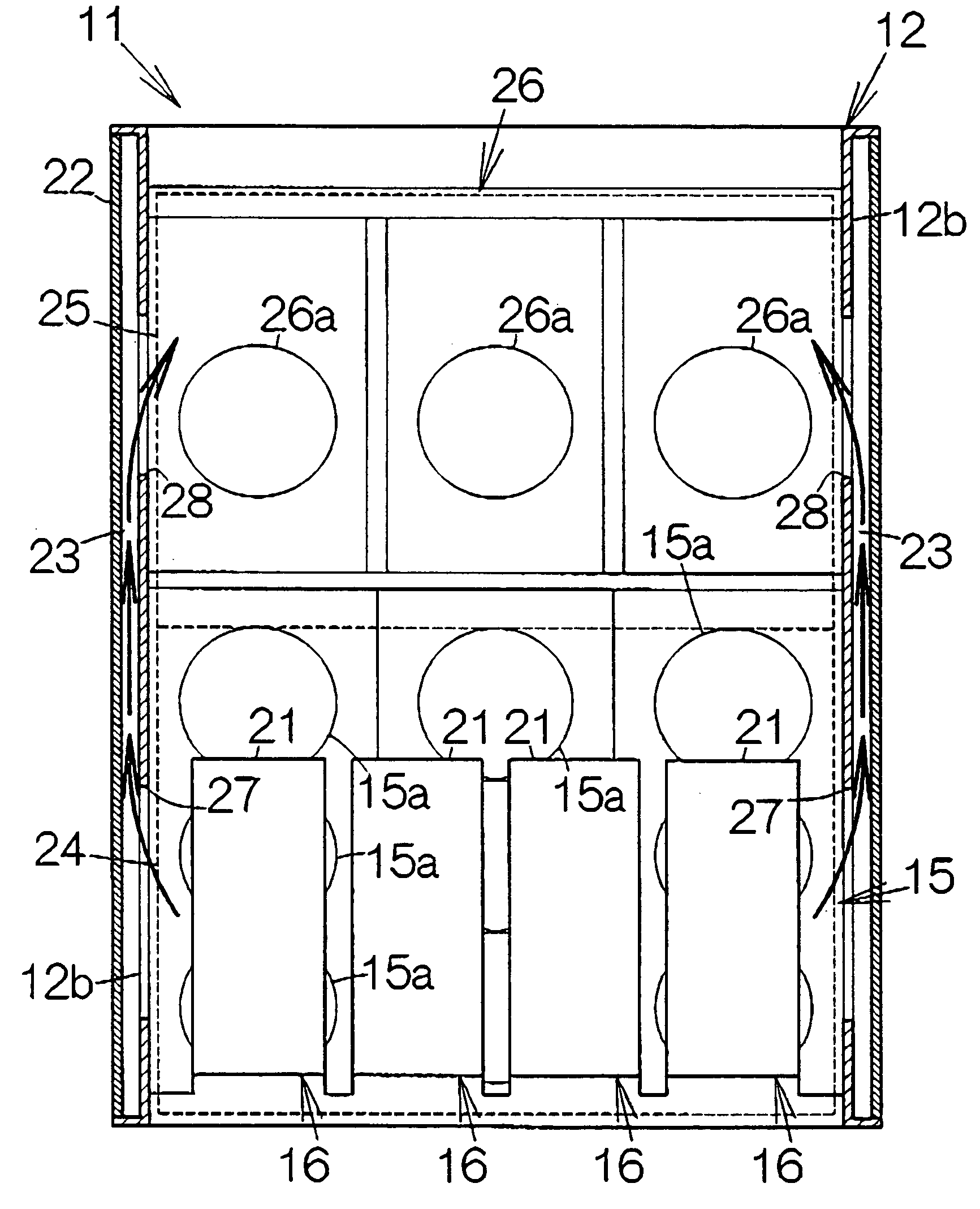
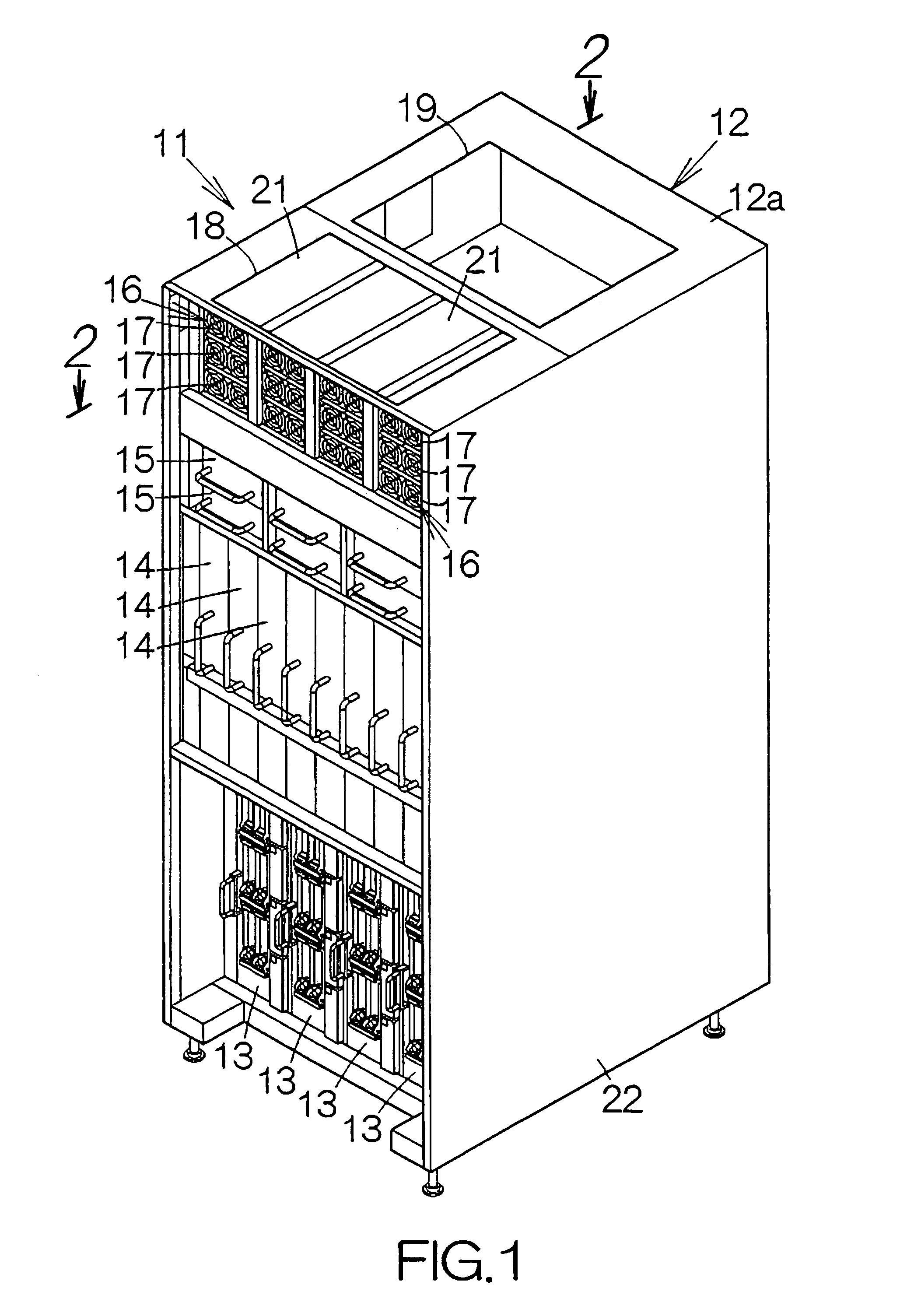
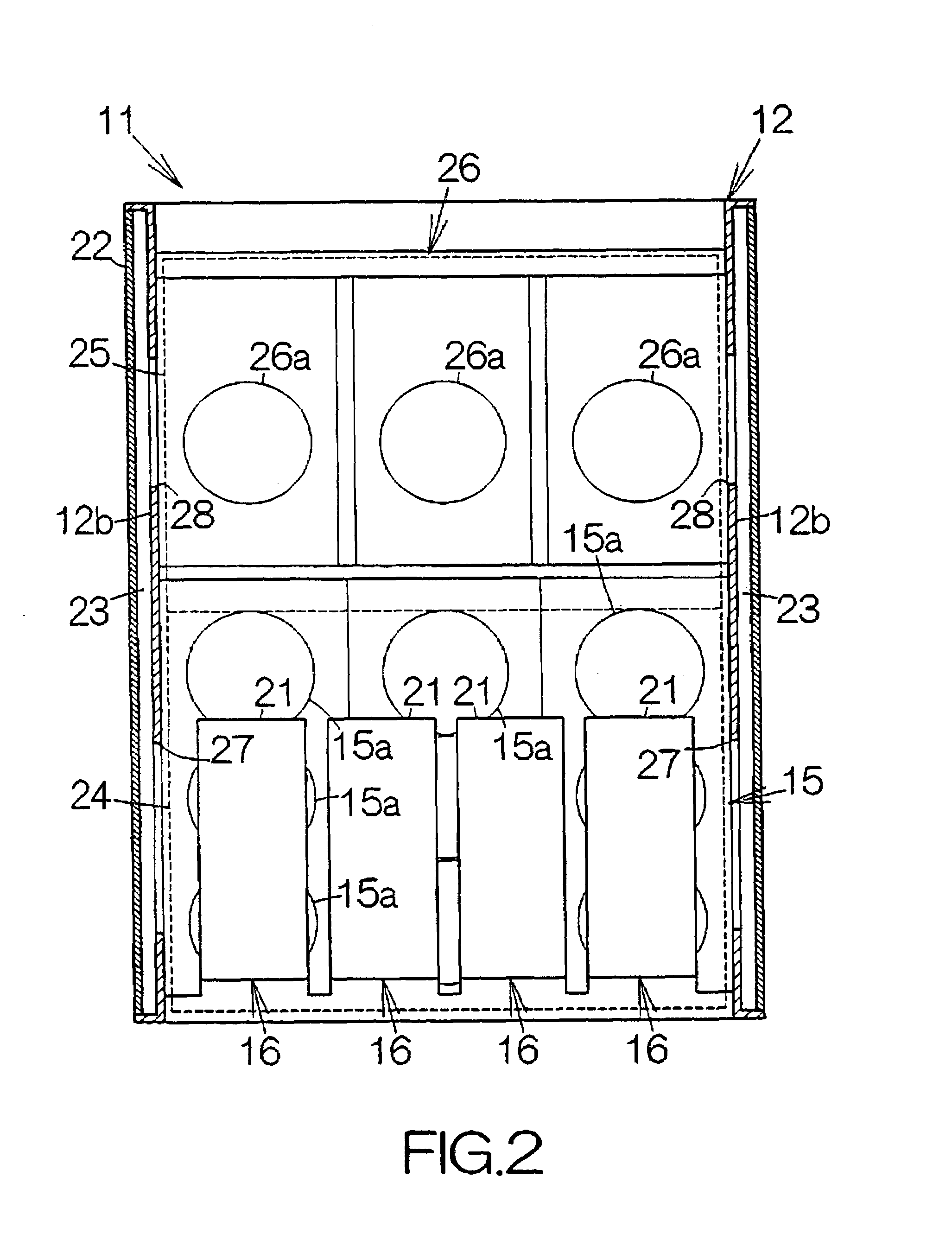
[0021]FIG. 1 schematically illustrates a server computer 11 as a specific example of an electronic apparatus according to the present invention. The server computer 11 includes an enclosure 12. Input / output units 13 are mounted on the lower rack of the enclosure 12. A PCI board is incorporated in the individual input / output unit 13. A LAN cable is coupled to the PCI board, for example. The PCI board stands upright in the vertical direction perpendicular to the floor.

[0022]System board units 14 are mounted on the middle rack of the enclosure 12. A system board is incorporated in the individual system board unit 14. Electronic circuit elements such as a central processing unit (CPU), a memory, and the like, are mounted on a printed wiring board of the system board, for example. The CPU executes various kinds of processing based on software programs and / or data temporarily stored in the memory, for example. The system board stands upright in the vertical direction.

[0023]Fan units 15 ar...


PUM


Abstract

Air in the first section is allowed to run into a second section through first and second air vents in an electronic apparatus. This causes an increase in the amount of airflow in the first section. In particular, if the pressure loss is larger in the first section, airflow blocked in the first section is forced to run into the second section. A smooth airflow can be established in the first section. Moreover, if the pressure in the first section is set larger than the pressure in the second section, a smoother airflow is established from the first section to the second section. A further superior airflow can be established in the first section.

Description

BACKGROUND OF THE INVENTION[0001]1. Field of the Invention[0002]The present invention relates to an electronic apparatus such as a server computer.[0003]2. Description of the Prior Art[0004]A back panel stands upright in the enclosure of a server computer, for example. System board units and input / output units are respectively coupled to the front and back surfaces of the back panel through connectors, for example. A fan unit or units are incorporated in the enclosure for the purpose of cooling these units. The fan unit serves to generate airflow running in the vertical direction through first and second spaces defined along the front and back surfaces of the back panel, respectively.[0005]Assume that a power source unit is mounted on the upper rack of the enclosure in the first space. The airflow generated by the fan unit collides against the bottom of the power source unit in the first space. On the contrary, the airflow is discharged out of the second space through an air outlet ...

Claims


Application Information

Patent Timeline
Patent Type & Authority Patents(United States)
IPC IPC(8): H05K7/20
CPCH05K7/20736
Inventor FUJIYA, HIROMITSUKIMURA, HIDEKI
Owner FUJITSU LTD
Why Eureka
Try Eureka