Airflow distribution to a low emissions combustor

a combustor and airflow technology, applied in the direction of machines/engines, stators, lighting and heating apparatus, etc., can solve the problems of rich fuel blowout, more unstable fuel-lean mixture, instabilities of combustion, etc., to reduce nox, reduce pressure drop, and increase combustion stability

Active Publication Date: 2009-06-04
ANSALDO ENERGIA SWITZERLAND AG
View PDF9 Cites 18 Cited by
  • Summary
  • Abstract
  • Description
  • Claims
  • Application Information

AI Technical Summary

Benefits of technology

[0006]An apparatus and method of providing a gas turbine combustor having increased combustion stability, lower NOx, reduced pressure drop across a gas turbine combustor, and higher efficiency is provided. A gas turbine combustor comprising a flow sleeve, combustion liner, at least one fuel nozzle, and a plurality of vanes fixed to the flow sleeve radially between the flow sleeve and combustion liner is d

Problems solved by technology

While premixing fuel and compressed air prior to combustion has its advantages in terms of emissions, it also has certain disadvantages such as combustion instabilities and more specifically combustion dynamics.
(Of course, if the fuel-air mixture becomes too fuel rich, the flame and combustion process becomes more unstable, and can lead to rich fuel blowout.)
Therefore, fuel-lean mixtures tend to be more unstable given the lesser fuel content for a given amount of air.
As a result, when fuel-lean mixtures are burned they tend to produce greater pressure fluctuations due to the unstable flame.
If the airflow is not uniform and not relatively free from swirl, the amount of air entering th

Method used


Image

  • Airflow distribution to a low emissions combustor
  • Airflow distribution to a low emissions combustor
  • Airflow distribution to a low emissions combustor

Examples


Embodiment Construction

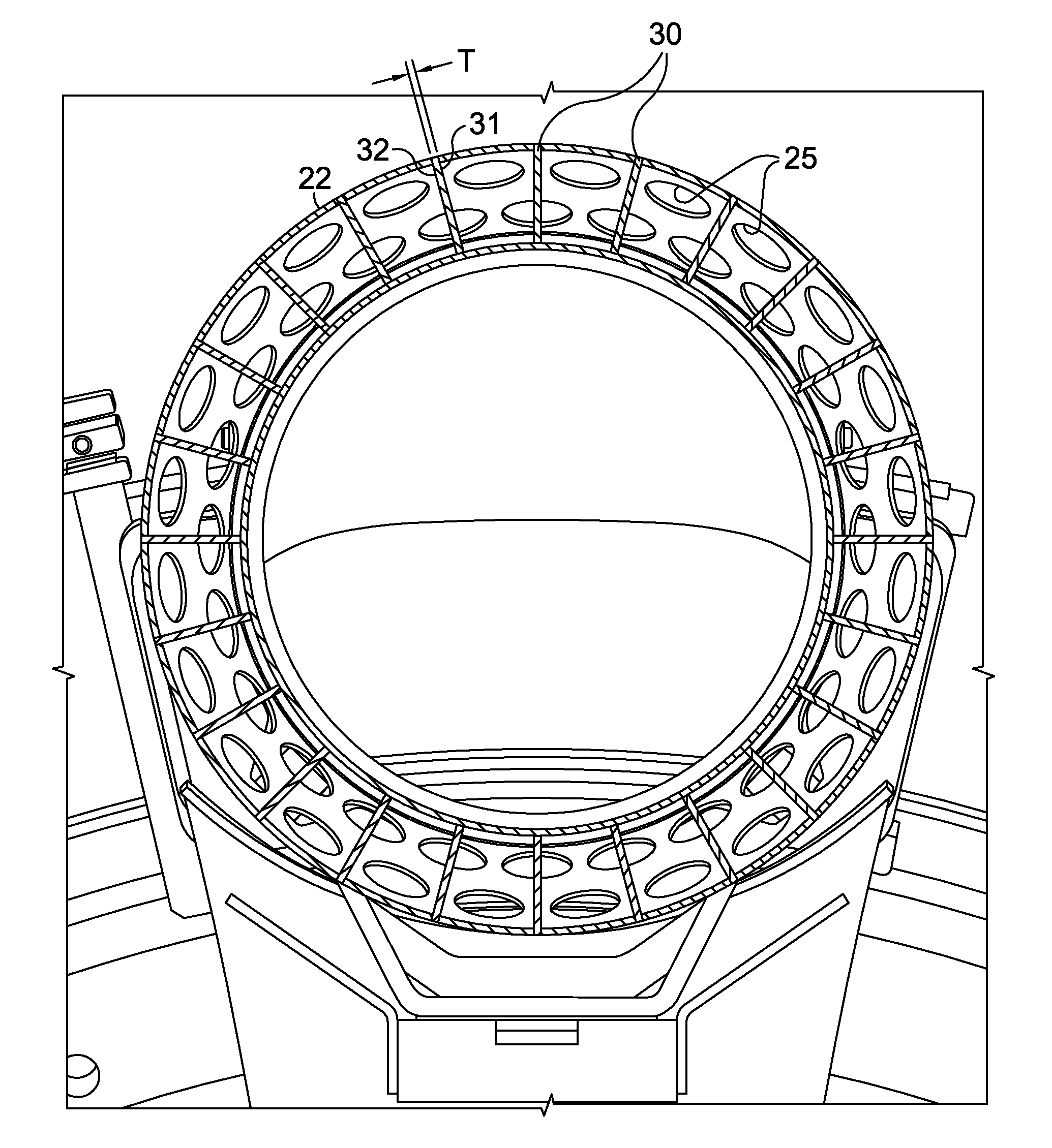
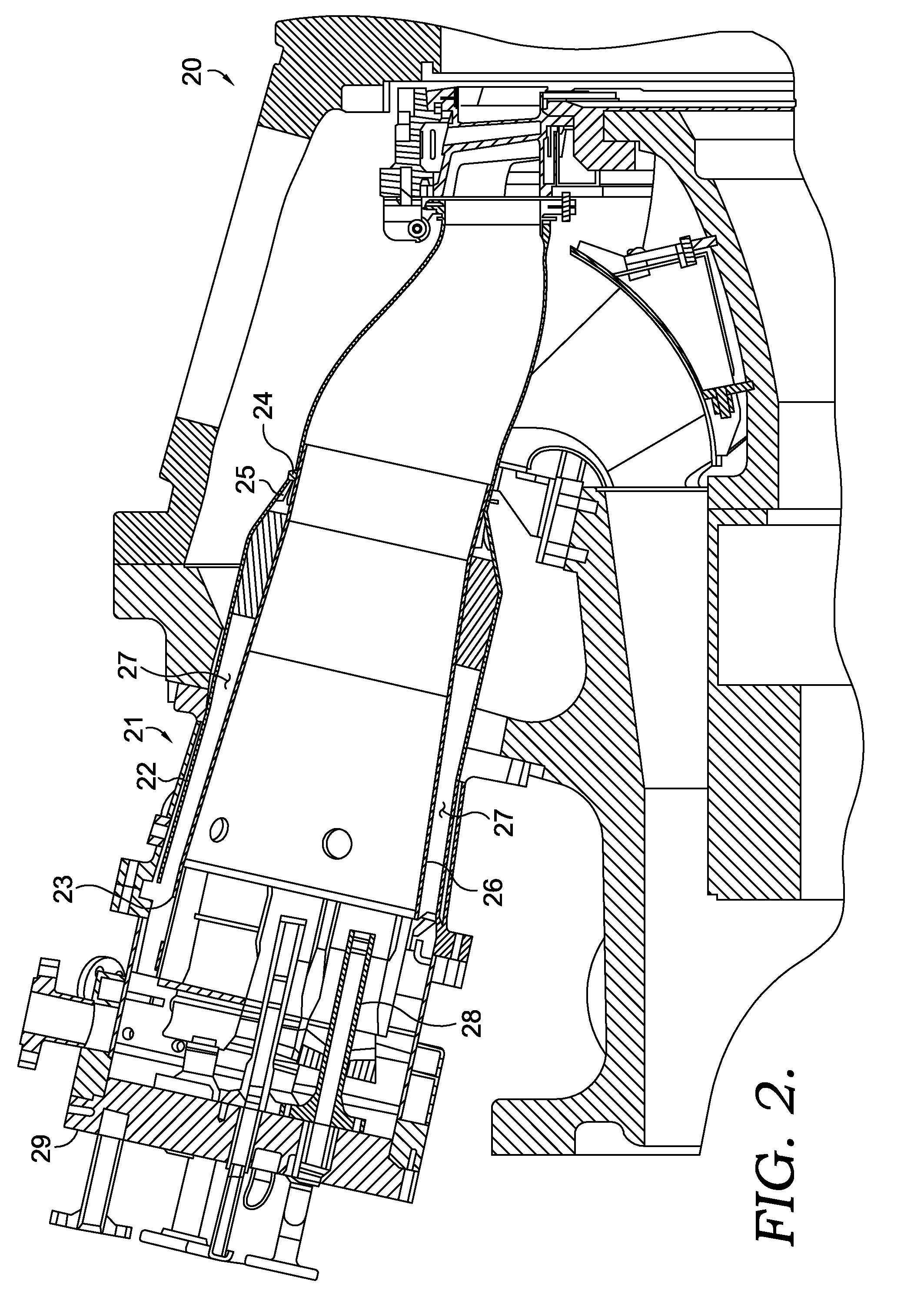
[0015]The preferred embodiment of the present invention will now be described in detail with particular reference to FIGS. 2-4. Referring to FIG. 2, a portion of gas turbine engine 20 is shown in cross section. In the preferred embodiment, a plurality of gas turbine combustors 21 are mounted to gas turbine engine 20, one of which is shown in FIG. 2. Combustor 21 comprises flow sleeve 22 having first end 23, second end 24, and a plurality of first holes 25 located proximate second end 24. In accordance with the preferred embodiment, plurality of first holes 25 is spaced axially in circumferential rows about flow sleeve 22 as shown in FIG. 4 and plurality of first holes 25 each preferably have a diameter of up to 2.50 inches. Located radially within flow sleeve 22 is combustion liner 26, thereby forming first passage 27 between combustion liner 26 and flow sleeve 22. Positioned at the forward end of combustion liner 26 for injecting a fuel to mix with air in combustion liner 26 is at ...


PUM


Abstract

An apparatus and method of providing a gas turbine combustor having increased combustion stability and reducing pressure drop across a gas turbine combustor is disclosed. A plurality of vanes is fixed to a flow sleeve radially between the flow sleeve and a combustion liner. The plurality of vanes serve to direct a flow of air entering the region between the flow sleeve and combustion liner in a substantially axial direction, such that components of tangential velocity are removed thereby providing a more uniform flow of air the combustion chamber and reducing the amount of pressure lost due attempting to straighten the airflow by pressure drop alone.

Description

TECHNICAL FIELD[0001]The present invention applies generally to gas turbine combustors and more specifically to an apparatus and method for providing improved combustion stability and lower pressure drop across the combustion system.BACKGROUND OF THE INVENTION[0002]In a combustion system for a gas turbine, fuel and compressed air are mixed together and ignited to produce hot combustion gases that drive a turbine and produce thrust or drive a shaft coupled to a generator for producing electricity. In an effort to reduce pollution levels, government agencies have introduced new regulations requiring gas turbine engines to reduce emitted levels of emissions, including carbon monoxide (CO) and oxides of nitrogen (NOx). A common type of combustion, employed to comply with these new emissions requirements, is premix combustion, where fuel and compressed air are mixed together prior to ignition to form as homogeneous a mixture as possible and burning this mixture to produce lower emissions...

Claims


Application Information

Patent Timeline
IPC IPC(8): F02C1/00
CPCF01D9/023F23R3/54F23R3/04
Inventor MARTLING, VINCENT C.XIAO, ZHENHUA
Owner ANSALDO ENERGIA SWITZERLAND AG
Why Eureka
Try Eureka