Gas turbogroup

a technology of gas turbogroup and turbofan, which is applied in the direction of machines/engines, mechanical equipment, lighting and heating apparatus, etc., can solve the problem of problem of reducing the pressure of the compressor by a little bit of cooling air in the middl

Active Publication Date: 2009-08-04
ANSALDO ENERGIA SWITZERLAND AG
View PDF21 Cites 22 Cited by
  • Summary
  • Abstract
  • Description
  • Claims
  • Application Information

AI Technical Summary

Benefits of technology

[0004]According to one aspect, the disclosure is based on the object of disclosing a gas turbogroup of the type mentioned in the introduction in such a way that an alternative to the prior art is created. According to a more specific aspect of the invention, a development of the prior art is to be disclosed. A further object upon which the invention is based can be seen as carrying out cooling of the second combustion chamber so that increased power output and improved efficiency of the gas turbogroup is achieved. A further aspect of the invention is to increase the mass flow and the volumetric flow in the high-pressure section of the gas turbogroup, and especially in the last stages of the compressor. A further effect, which is achieved by means of the invention, is to increase the combustion stability by means of preheating the combustion air during premix combustion in the first combustion chamber, and / or to reduce the formation of nitrogen oxide. A further effect of the invention is to avoid the arrangement of an intermediate tapping point of the compressor.
[0005]A gas turbogroup is disclosed, comprising a compressor, a first combustion chamber, a first turbine, a second combustion chamber, and a second turbine, wherein the first combustion chamber is arranged downstream of the compressor, the first turbine is arranged downstream of the first combustion chamber, the second combustion chamber is arranged downstream of the first turbine, and the second turbine is arranged downstream of the second combustion chamber, in which gas turbogroup the second combustion chamber has a convectively cooled wall, wherein a cooling air feed line for the second combustion chamber branches from the main flow path of the gas turbogroup downstream of the compressor and upstream of the first combustion chamber, and in that a return line for heated cooling air leads from the second combustion chamber upstream of the first turbine to the main flow path.

Problems solved by technology

In WO 03 / 038255, operating states of the gas turbogroup are described, in which the pressure build-up inside the compressor is shifted, and the intermediate tapping of cooling air at reduced pressure from the compressor can be problematical.

Method used


Image

  • Gas turbogroup
  • Gas turbogroup
  • Gas turbogroup

Examples


Embodiment Construction

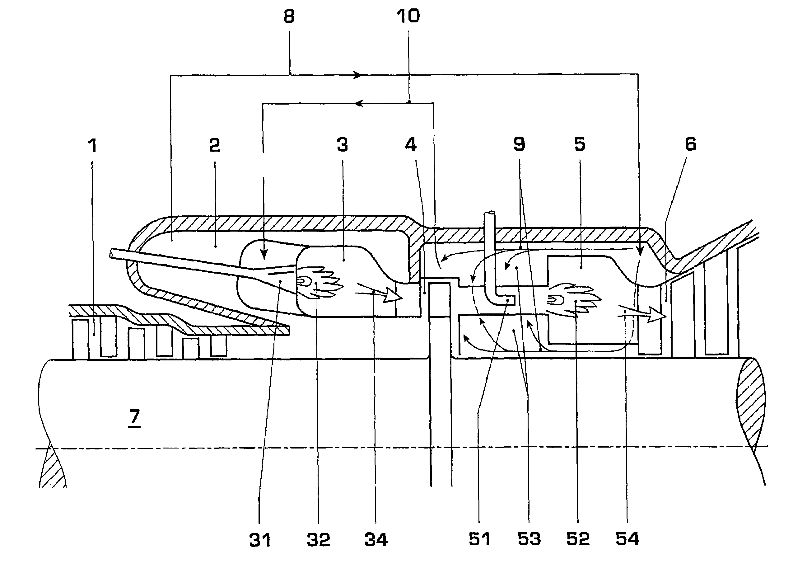
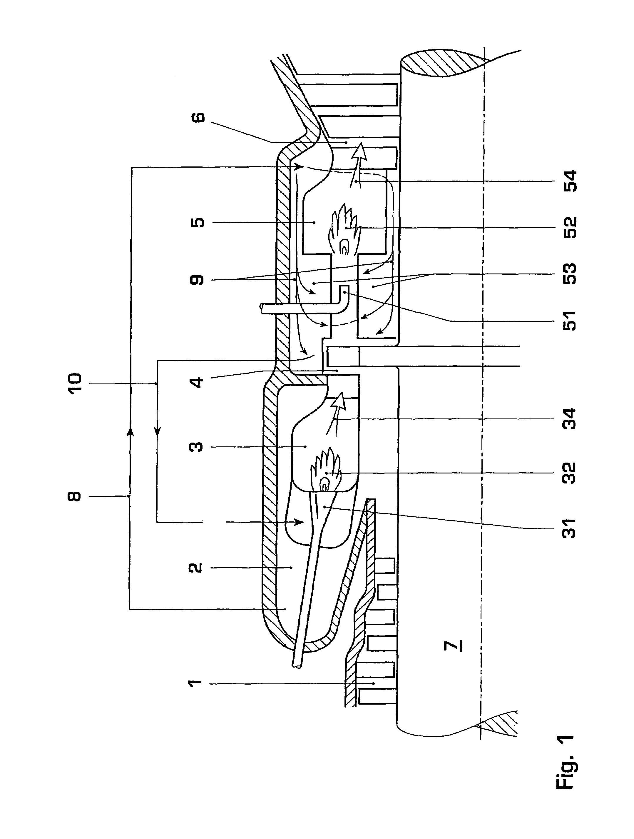
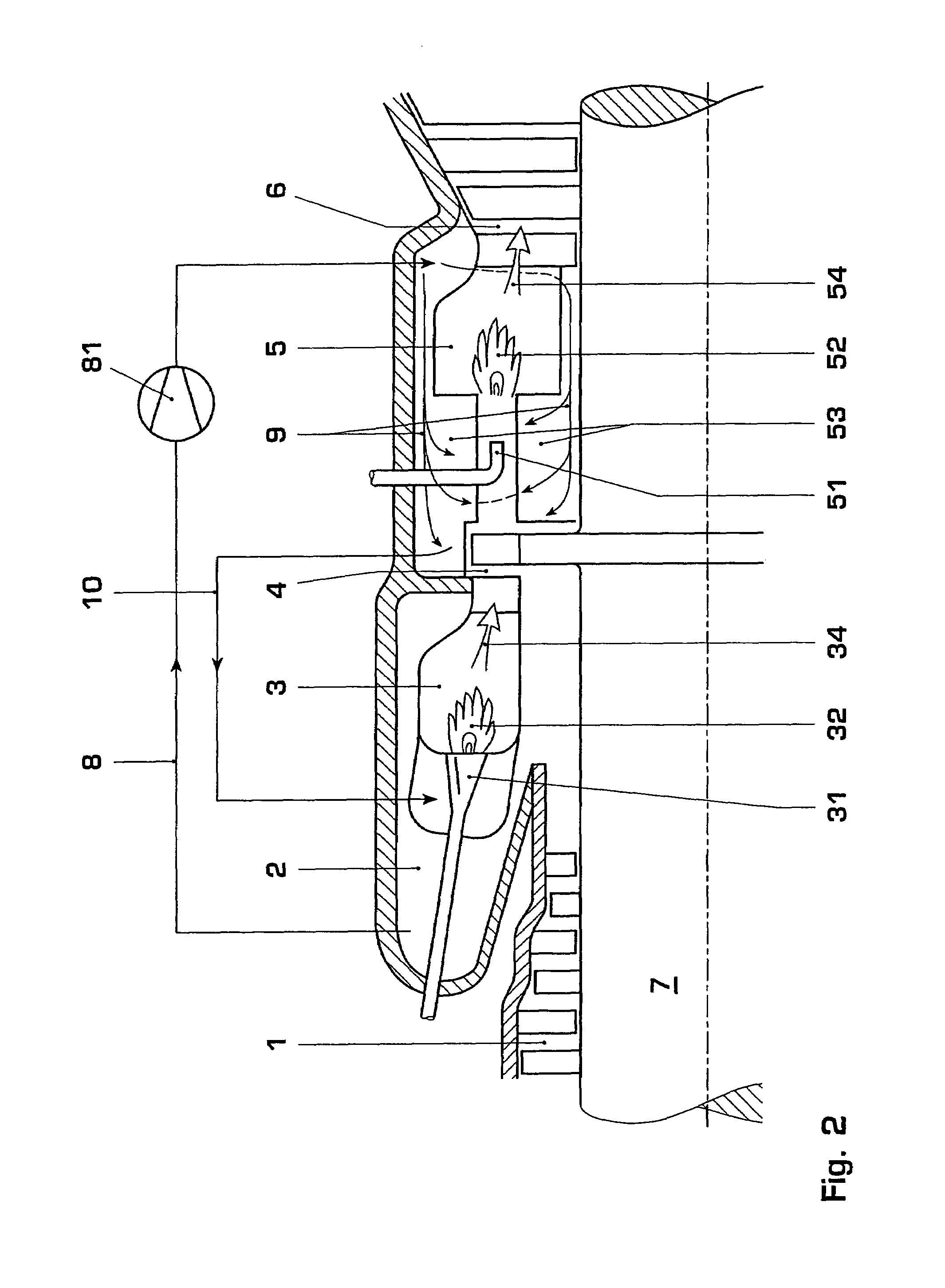
[0012]In an exemplary gas turbogroup, the cooling air for the second combustion chamber is tapped from the main flow path of the gas turbogroup downstream of the compressor and upstream of the first combustion chamber. This cooling air is then guided to the second combustion chamber of the gas turbogroup, and flows over the surface, which faces away from the combustion zone, of the combustion chamber wall of the second combustion chamber. In the process, the combustion chamber wall is convectively cooled by the overflowing cooling air absorbing heat from the combustion chamber wall. The cooling air flow, in one exemplary embodiment of the disclosure, is guided in counterflow towards the hot gas flow, or reaction flow, which flows inside the combustion chamber. The cooling air is heated in the process. After subsequent cooling, the used cooling air is again introduced into the main flow path of the gas turbogroup upstream of the first turbine. In this way, the pressurized and heated ...


PUM


Abstract

In a gas turbogroup, which comprises a compressor, a first combustion chamber, a first turbine, a second combustion chamber, and a second turbine, the first combustion chamber is arranged downstream of the compressor, the first turbine is arranged downstream of the first combustion chamber, the second combustion chamber is arranged downstream of the first turbine, and the second turbine is arranged downstream of the second combustion chamber, wherein the second combustion chamber has a convectively cooled wall. A cooling air feed line for the second combustion chamber branches from the main flow path of the gas turbogroup downstream of the compressor and upstream of the first combustion chamber. A return line for heated cooling air leads from the second combustion chamber upstream of the first turbine to the main flow path.

Description

RELATED APPLICATIONS[0001]This application claims priority under 35 U.S.C. §119 to German Application No. 10 2005 042 889.4 filed in Germany on 9 Sep. 2005, and as a continuation application under 35 U.S.C. §120 to PCT / EP2006 / 065359 filed as an International Application on 16 Aug. 2006 designating the U.S., the entire contents of which are hereby incorporated by reference in their entireties.TECHNICAL FIELD[0002]A gas turbogroup is disclosed.BACKGROUND INFORMATION[0003]A gas turbogroup with so-called sequential combustion has become known from EP 620 362. In this gas turbogroup, a first turbine is arranged downstream of a first combustion chamber, a second combustion chamber is arranged downstream of the first turbine, and a second turbine is arranged downstream of the second combustion chamber. In this case, the second combustion chamber is constructed as a so-called auto-ignition combustion chamber. The cooling of such a combustion chamber is described in EP 669 500. There, the co...

Claims


Application Information

Patent Timeline
Patent Type & Authority Patents(United States)
IPC IPC(8): F02C7/12F02C7/18
CPCF02C6/003F02C7/12F23R2900/03341F23D2214/00F05D2260/205F23D2206/10
Inventor ALTHAUS, ROLF
Owner ANSALDO ENERGIA SWITZERLAND AG
Why Eureka
Try Eureka