Electrode for obtaining a biopotential signal

a biopotential signal and electrode technology, applied in the field of electrodes for obtaining biopotential signals, can solve the problems of simple construction and low cost, and achieve the effects of low cost, good use effect and practical us

a biopotential signal and electrode technology, applied in the field of electrodes for obtaining biopotential signals, can solve the problems of simple construction and low cost, and achieve the effects of low cost, good use effect and practical us

US7366558B2Active Publication Date: 2008-04-29GENERAL ELECTRIC CO

Image

  • Electrode for obtaining a biopotential signal
  • Electrode for obtaining a biopotential signal
  • Electrode for obtaining a biopotential signal

Examples


Embodiment Construction

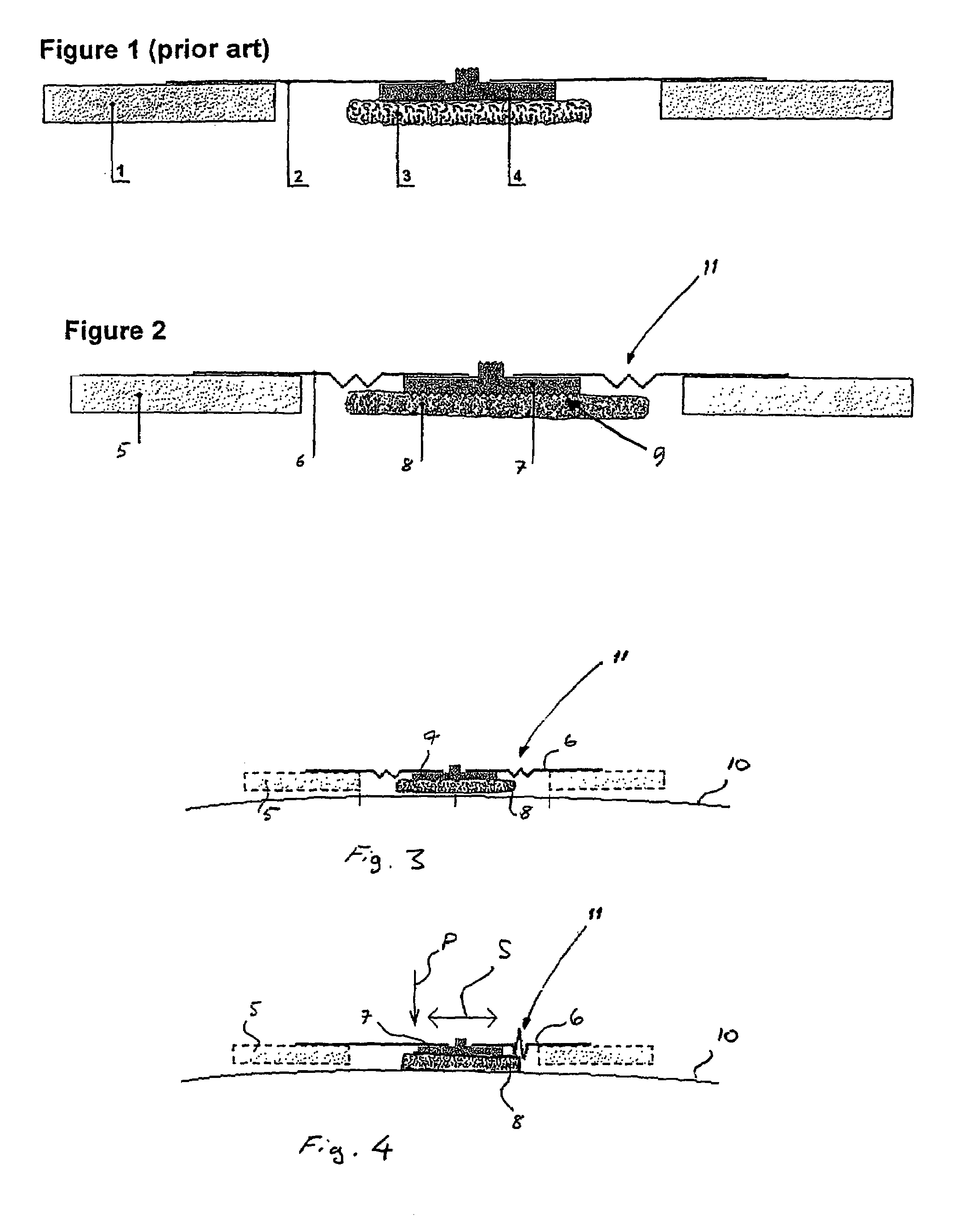
[0022]FIG. 1 shows a typical example of the prior art. The electrode consists of an adhesive element, i.e. an adhesive foam tape 1, electrode body 2 made of shaped plastic film, abrasive harsh sponge 3 soaked with conductive gel, and an electrode pad 4. The abrasive sponge 3 functions as a preparation instrument and a gel carrier. Movement of the electrode part and the abrasive sponge relative to the skin surface performs the preparation. A coarse sponge 3 rasps the skin surface and makes the abrasion. An abrasive sponge can be manufactured of e.g. stiff cellular plastic. The elements described above are advantageously circular elements.

[0023]In the electrode of the prior art described above the sponge 3, i.e. the abrasive element, is always in contact with the skin when the electrode is attached to the skin. This leads to the disadvantages described earlier in the text.

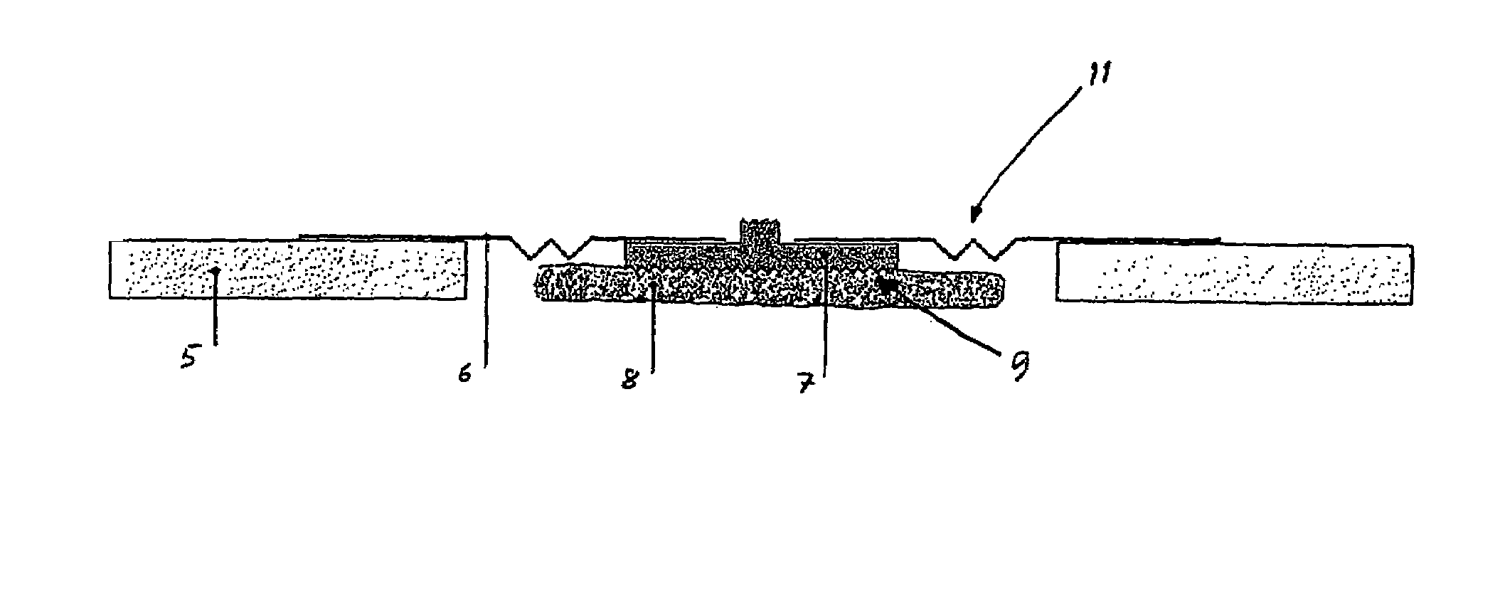
[0024]FIG. 2 shows one embodiment of the invention. Reference number 5 shows an adhesive element, which can be for...


PUM


Abstract

An electrode for obtaining a biopotential signal from the skin of a subject. The electrode comprises an adhesive element, an electrode body, an electrically conductive electrode pad, a sponge element, soaked with conductive gel, and means for skin abrasion. The means for skin abrasion comprises abrasion elements forming an integrated structure with the electrode pad, the abrasion elements being so dimensioned that the sponge element prevents the abrasion elements from touching the skin when biopotential signals are measured and enables mechanical contact between the skin and the abrasion elements when the electrode pad is pushed towards the skin. The electrode body is made flexible to enable intentional movement of the electrode pad relative to the adhesive element.

Description

CROSS REFERENCE TO RELATED APPLICATION[0001]The present application claims priority from Finnish Patent Application No. 20055366, filed Jun. 30, 2005.BACKGROUND OF THE INVENTION[0002]The invention relates to an electrode for obtaining a biopotential signal from the skin of a subject, the electrode comprising an adhesive element, an electrode body, an electrically conducting electrode pad, a sponge element, soaked with conductive gel, and means for skin abrasion.[0003]Diagnostic tests, treatments and the presence of illness require obtaining and monitoring electrical signals generated by the physiological functioning of a patient. Typical electrical signals or biopotentials commonly monitored are those producing electrocardiograms (ECG) from the heart, electroencephalograms (EEG) from the brain and electromyograms (EMG) from muscles. While the duration of most of the biopotential recordings are of the order of one hour, for example intensive care patients may benefit from continuous ...

Claims


Application Information

Patent Timeline
29 Apr 2008
Publication
US7366558B2
IPC
A61B5/04; A61B; A61B5/296
CPC
A61B5/04025; A61B5/0408; A61B5/0478; A61B5/0492; A61B5/325; A61B5/25; A61B5/291; A61B5/296
Inventors
VIRTANEN, JUHA; SAVINEN, OUTI