Warm bath apparatus

a technology of warm bath and apparatus, which is applied in the field of warm bath apparatus, can solve the problems of loss of part of the heat of the mixture, and achieve the effect of safe and uniform warm bath effect and high degree of satisfaction

Inactive Publication Date: 2008-05-06
MATSUSHITA ELECTRIC WORKS LTD
View PDF13 Cites 5 Cited by
  • Summary
  • Abstract
  • Description
  • Claims
  • Application Information

AI Technical Summary

Benefits of technology

[0008]Therefore, a primary concern of the present invention is to provide a compact warm bath apparatus having the capability of safely providing a uniform warm bath effect to a user, and particularly people suffering from sensitivity to cold with a high degree of satisfaction.
[0010]In the warm bath apparatus of the present invention, after heated liquid particles such as steam generated by the heater are previously mixed with a required amount of the air in the mixing room, the resultant mixture is supplied as a bathing medium to the warm bath room. Therefore, it is possible to remarkably decrease a variation in distribution of the heated liquid particles in the warm bath room and uniformly warm the part of the living body, as compared with a conventional case of diffusing steam particles by use of a fan disposed in a warm bath room. In addition, since the steam particles of a high temperature are not directly supplied into the warm bath room, it is possible to prevent burn injury and effectively reduce the internal volume of the warm bath room. In other words, the heated liquid particles are suitably cooled by previously mixing with the air, so that the resultant mixture of a desired temperature can be supplied as the bathing medium into the warm bath room. Thus, according to the present invention, the warm bath apparatus can be designed in compact size to safely provide a warm bath therapy effect to the user with a high degree of satisfaction.
[0011]It is preferred that the above warm bath apparatus further comprises an air intake channel for supplying the air in the warm bath room into the mixing room. In this case, the air in the warm bath room is supplied into the mixing room through the air intake channel, and then mixed with the heated liquid particles, so that the resultant mixture is supplied into the warm bath room thorough the supply port. Since the part of the living body is warmed by the mixture in the warm bath room, a part of heat of the mixture is lost. However, the used mixture is sufficiently higher in temperature than the air outside the warm bath apparatus. Therefore, when the used mixture is sent to the mixing room through the air intake channel, and then mixed with the heated liquid particles provided through the liquid-particle intake channel in the mixing room, it is possible to save amounts of the heated liquid particles needed to reproduce the mixture to be supplied into the warm bath room. Thus, the formation of the air intake channel for recycling the used mixture is effective to present the warm bath apparatus of energy-saving type.
[0012]It is also preferred that the above warm bath apparatus further comprises suction means such as a fan for sucking the air in the warm bath room into the air intake channel. In this case, it is possible to stably supply the air into the mixing room. In addition, there is an advantage that a mixture ratio of the air and the heated liquid particles can be changed by controlling the fan.
[0013]It is also preferred that the above warm bath apparatus further comprises a liquid-particle intake channel for supplying the heated liquid particles generated by the heater to the mixing room, a converging portion for joining the liquid-particle intake channel with the air intake channel, and a single fan disposed in the converging portion to simultaneously supply both of the air provided from the air intake channel and the heated liquid particles provided from the liquid-particle intake channel into the mixing room. This case is particularly suitable to realize a compact warm bath apparatus excellent in energy-saving performance.

Problems solved by technology

Since the part of the living body is warmed by the mixture in the warm bath room, a part of heat of the mixture is lost.

Method used


Image

  • Warm bath apparatus
  • Warm bath apparatus
  • Warm bath apparatus

Examples


Embodiment Construction

[0028]As a preferred embodiment of a warm bath apparatus of the present invention, a foot bath apparatus is explained below.

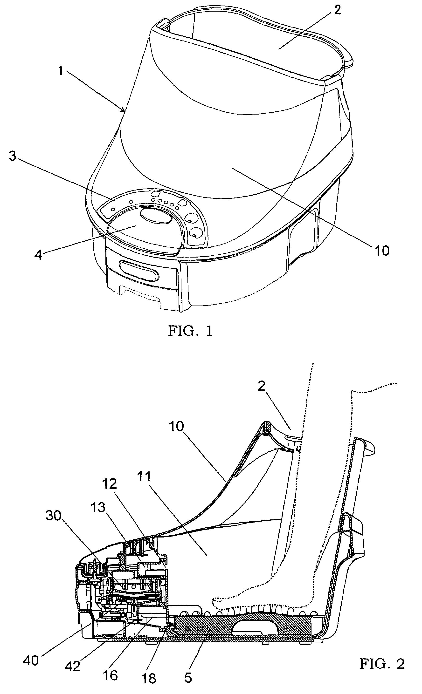
[0029]As shown in FIG. 1, this foot bath apparatus 1 is configured in a boot shape, in which both feet of a user can be inserted from a top opening 2. The numeral 3 designates an operation panel provided at the front side of the foot bath apparatus 1, at which a main power switch and buttons for setting bathing conditions are arranged. The numeral 4 designates a feed water tank detachably attached to a housing 10 of the foot bath apparatus.

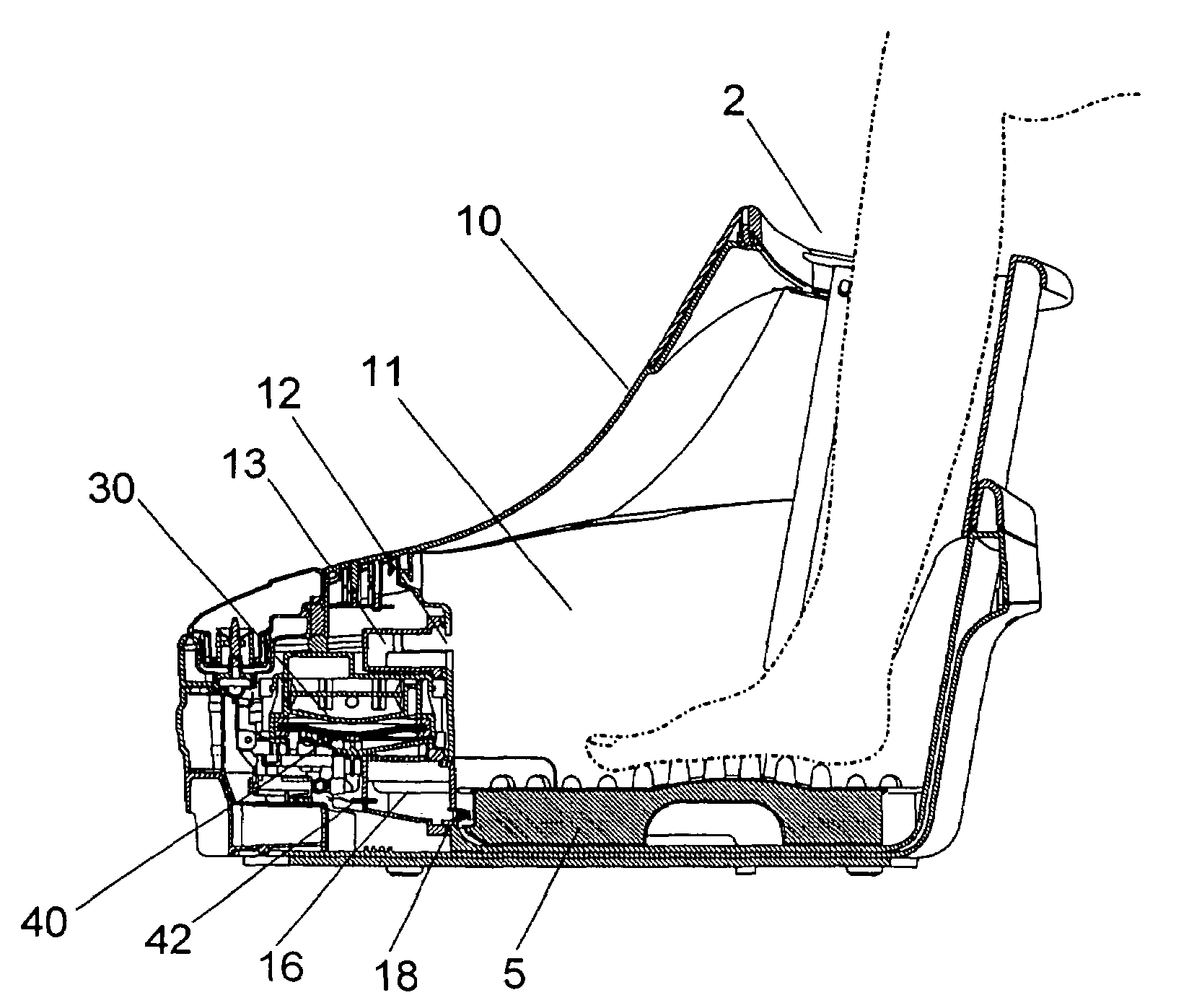
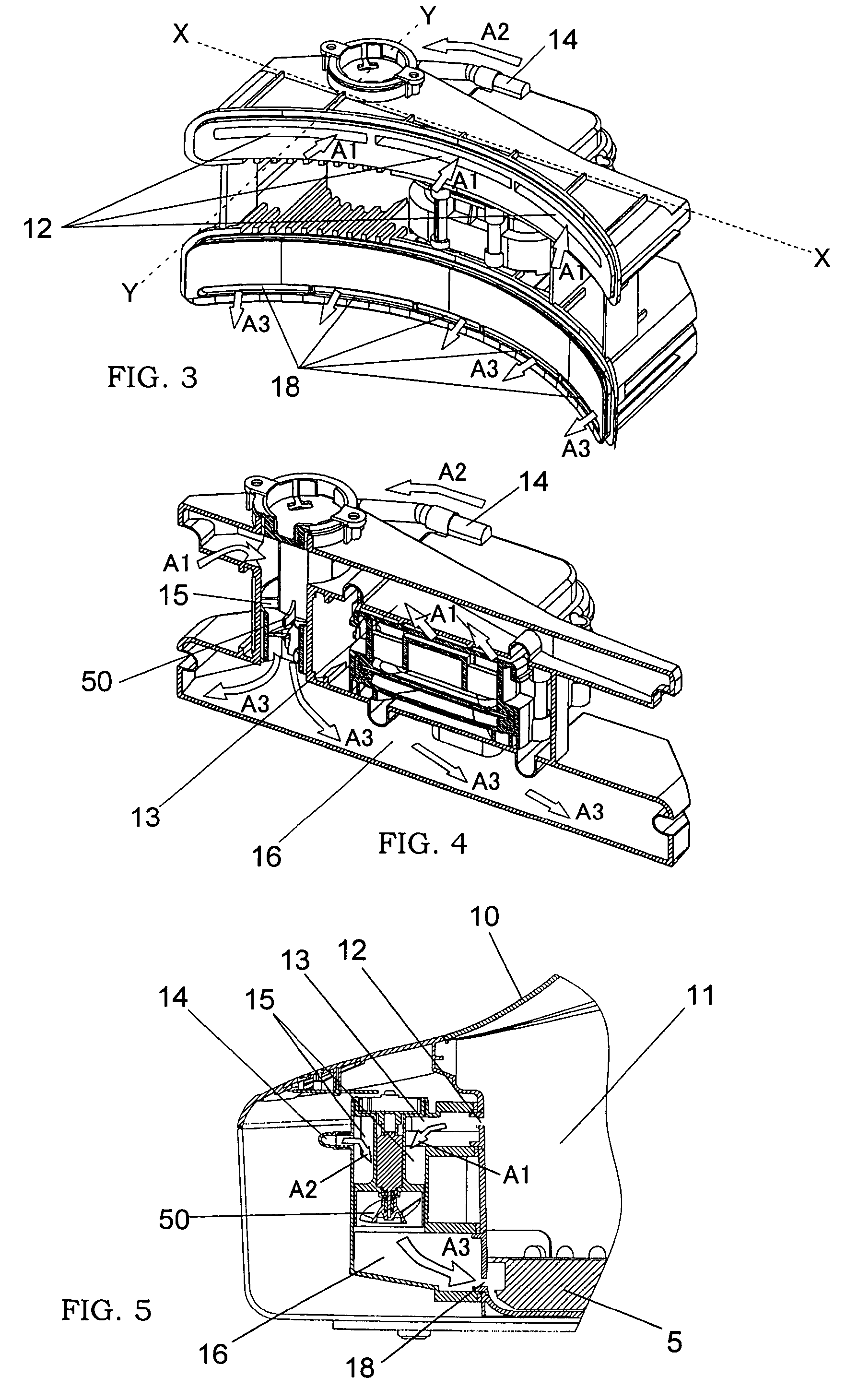
[0030]As shown in FIG. 2, this foot bath apparatus 1 is formed with the housing 10 having a foot bath room 11 therein, a built-in tank 30 for receiving water from the feed water tank 4 and storing a required amount of water, a heater 40 for heating water in the built-in tank 30 to generate heated water particles, i.e., steam, suction port 12 formed in an inner wall facing the foot bath room 11, air intake channel 13 connected...


PUM

PropertyMeasurementUnit
temperatureaaaaaaaaaa
bathing temperatureaaaaaaaaaa
sizeaaaaaaaaaa

Abstract

A warm bath apparatus for safely and comfortably warming a part of a user's body such as feet and hands by use of a previously prepared mixture of air and heated liquid particles such as steam is provided. This apparatus comprises a housing having a warm bath room, a tank for storing a liquid, a heater for heating the liquid to provide heated liquid particles, a mixing room separately formed from the warm bath room in the housing to mix the heated liquid particles with air; and a supply port for supplying a resultant mixture of the heated liquid particle and the air provided from the mixing room into the warm bath room According to this apparatus, it is possible to provide a warm bath therapy effect to the user suffering from sensitivity to cold with a high degree of satisfaction.

Description

BACKGROUND OF THE INVENTION[0001]1. Field of the Invention[0002]The present invention relates to a warm bath apparatus for warming a part of a living body such as feet and hands by use of heated liquid particles such as steam.[0003]2. Disclosure of the Prior Art[0004]In recent years, living environments fully equipped for air-conditioning and heating or excessive dieting lead to lessening the function of regulating body temperature, so that people suffering from sensitivity to cold are increasing. Since it is thought that the sensitivity to cold is caused by bad circulation of blood, facilitating the flow of blood by bathing or exercising is effective for the people suffering from the sensitivity to cold.[0005]For example, Japanese Patent Early Publication No. 11-89909 discloses a foot bath apparatus for bathing a user's feet in hot water. This apparatus 100, as shown in FIG. 11, comprises a bath vessel 110 having a top opening, heater 120 for heating water in the bath vessel and a ...

Claims


Application Information

Patent Timeline
Patent Type & Authority Patents(United States)
IPC IPC(8): E03C1/00A61H33/02A47K3/022A61H35/00B01F23/10
CPCA61H35/006A61H33/6089A61H33/02A47K3/022
Inventor WATANABE, SHUNICHIKUGUMIYA, SHIGENORIOHMURA, SHINGO
Owner MATSUSHITA ELECTRIC WORKS LTD
Why Eureka
Try Eureka