Endless track for high speed multi-terrain vehicles

a multi-terrain vehicle and end-to-end technology, applied in endless track vehicles, mechanical equipment, transportation and packaging, etc., can solve the problems of increasing energy costs of driving over flat, hard surfaces, and insufficient load of load-carrying off-road vehicles, so as to prevent severe twisting of track belts, reduce lateral “roll-out”, and improve performance

Inactive Publication Date: 2008-05-06
TORVEC INC
View PDF18 Cites 42 Cited by
  • Summary
  • Abstract
  • Description
  • Claims
  • Application Information

AI Technical Summary

Benefits of technology

[0015]In the improved track design disclosed, a cantilever cut, preferably a fore-and-aft cut, is made in each terrain-contacting lug just outboard of the track's main section. This cut significantly reduces lateral “roll-out” of the guide lugs from between the two supporting dual wheels when traversing uneven surfaces. That is, when the outer edge of the track passes over a sharply uneven terrain, this cut in each tapered lug allows the outer edge of the track belt to lift away from the flat surface of the main section under the wheels, thereby preventing severe twisting of the track belt that might otherwise cause the guide lugs to tip out of the mating surfaces formed between the two supporting dual wheels. While the invention is applicable to endless tracks for all track-laying vehicles, it particularly improves the performance of such new track-laying all-terrain vehicles of the type specifically designed for normal speed travel over paved highways as well as for appropriate use over unpaved roads and uneven off-road terrain.

Problems solved by technology

Unfortunately, almost all available automotive vehicles require infrastructure, including paved highways and bridges, for practical operation, and the developing countries are decades away from having the necessary infrastructure for such conventional vehicles.
While the latter frictional resistive forces are a valuable attribute under wet or snowy conditions, they add undesirably to energy costs when driving the vehicle over flat, hard surfaces.
Prior to the present inventor's track design, load-carrying off-road vehicles had either very large wheels or very cumbersome tracks, which are heavy, slow-moving, and inappropriate for use on paved roads at normal highway speeds.
While smaller all-terrain wheeled vehicles are commercially available, these do not carry adequate loads for normal multi-passenger or produce transport, and their drive wheels can easily become mired in heavy mud or snow.
Although the track designs patented in U.S. Pat. No. 6,241,327 offer superior combinations of off-road, highway speed, and load carrying capabilities, the present inventor has found that under certain conditions the endless track may experience an undesirable “roll-out”.
That is, when only the outer edge of the track passes over a sharply uneven terrain, a severe twisting of the track belt can, in some instances, cause the guide lugs to tip out of the mating surfaces formed between the two supporting dual wheels, thereby dislodging the endless track laterally out of its normal alignment.

Method used


Image

  • Endless track for high speed multi-terrain vehicles
  • Endless track for high speed multi-terrain vehicles
  • Endless track for high speed multi-terrain vehicles

Examples


Embodiment Construction

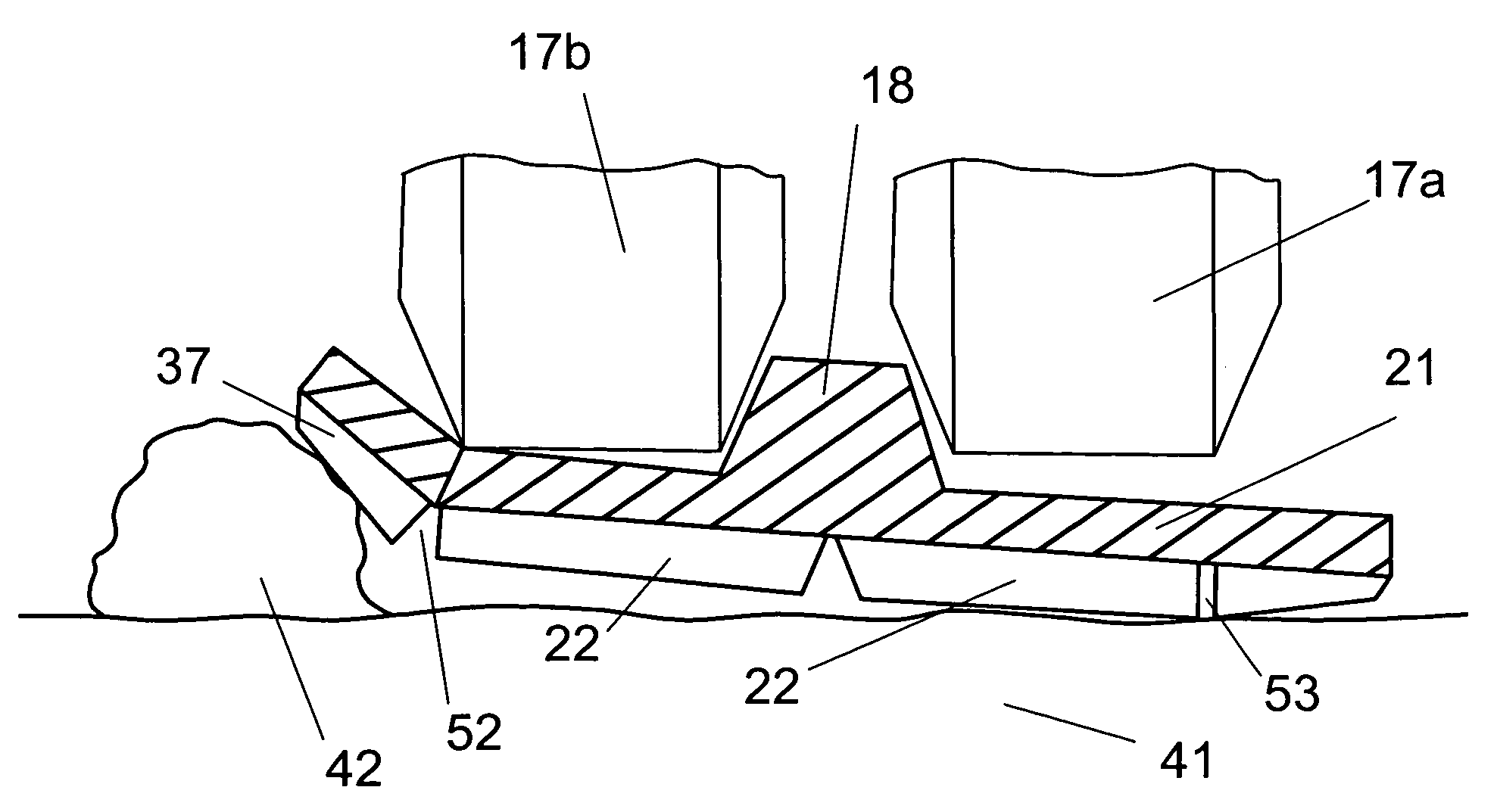
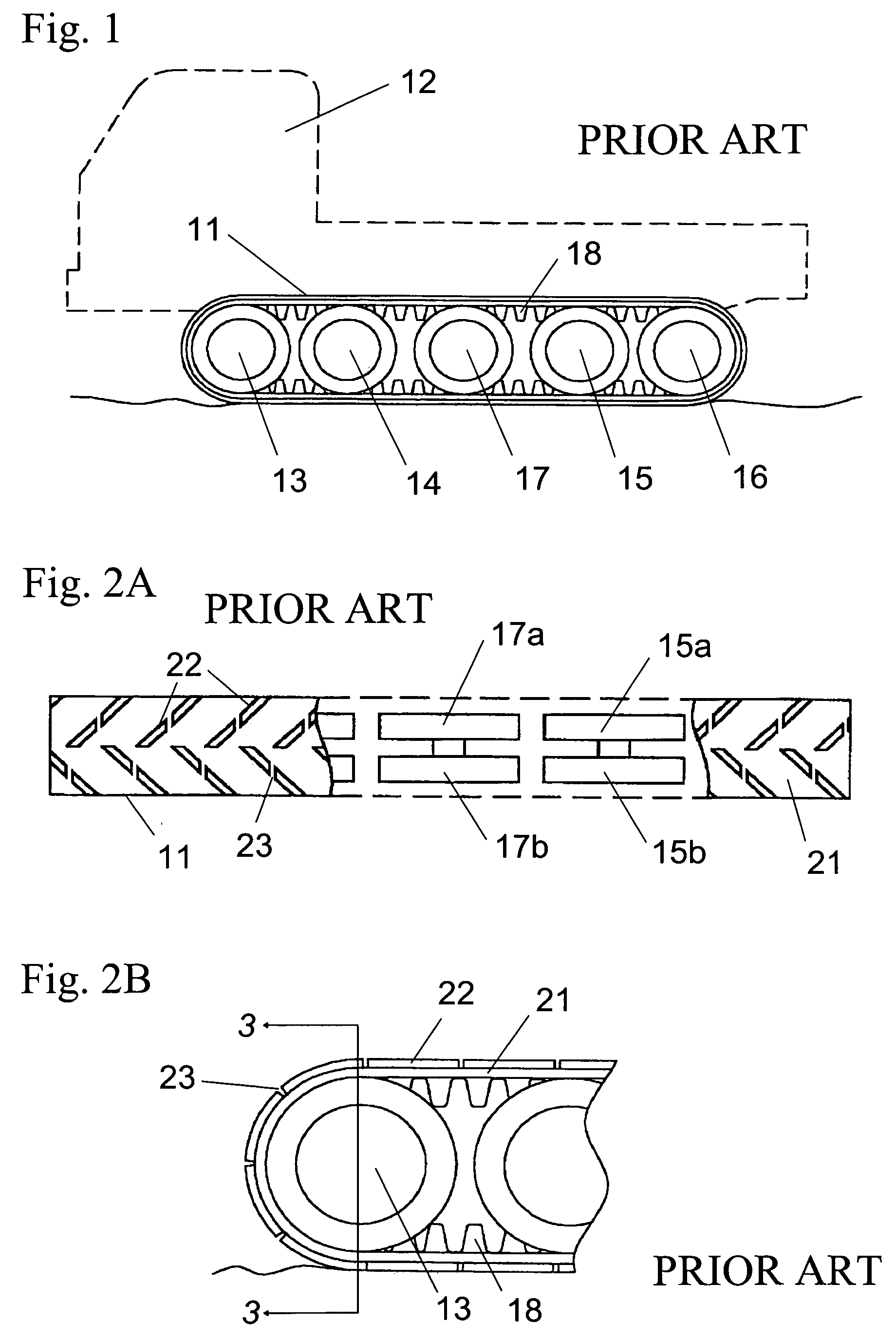
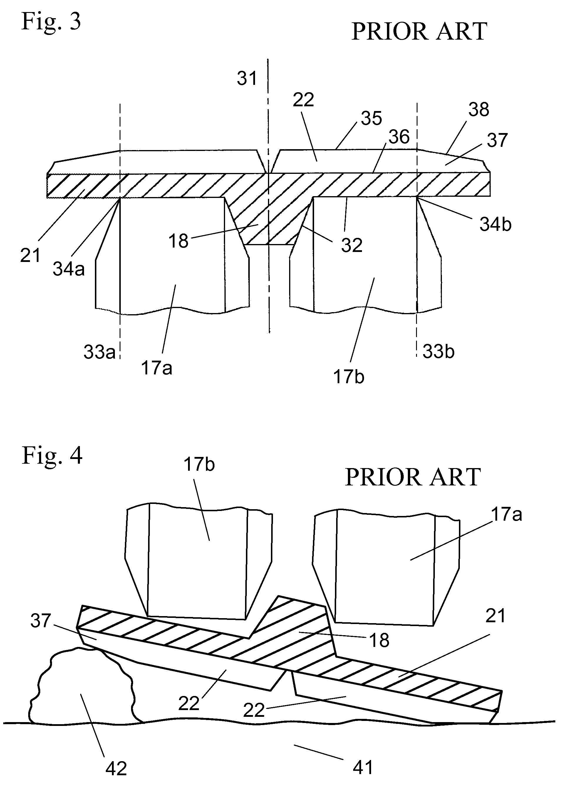
[0028]The invention herein modifies the outward-facing tread of a conventional rubber track to reduce instances of track roll-out, where the endless track may be dislodged laterally out of its normal alignment during operation of the vehicle. A cut is made down into the outward side of each tread just outboard of the position where the inside of the track contacts the outboard edge of the tread of the outer of the dual wheels of each pair of track-supporting dual wheels. While the invention is generally applicable to most rubber endless tracks, the just-described prior art track illustrated schematically in FIGS. 1 through 3 represents a specialized design disclosed in U.S. Pat. No. 6,241,327, for which the present invention is especially applicable. This specialized track is not sprocket-driven but instead is stretched over wheels covered with rubber tires and is driven solely by frictional contact between the tires and the interior surface of the track. The present invention has p...


PUM


Abstract

The track design for use with a tracked vehicle includes a cantilever cut made down into the outward side of each tread just outboard of the position where the inside of the track contacts the outboard edge of the tread of the outer wheel of each pair of track-supporting dual wheels. This cut significantly reduces lateral “roll-out” of the guide lugs from between the dual wheels when traversing uneven surfaces. When the outer edge of the track passes over sharply uneven terrain, this cut in the tread allows the outer edge of the track belt to lift away from the flat main surface under the wheels. Thus the interior surface of the track maintains contact with both tires of each pair of dual wheels by reducing twisting of the track belt that may cause the guide lugs to tip out of the mating surfaces formed between the dual-wheel pairs.

Description

BACKGROUND OF THE INVENTION[0001]1. Field of the Invention[0002]The invention pertains to the field of endless tracks used to propel track-laying vehicles. More particularly, the invention pertains to an improved track design for a track-laying vehicle.[0003]2. Description of Related Art[0004]Many track-laying vehicles are driven and supported by rubber tracks. As used herein, the term “rubber” relates to any elastic and primarily non-metallic materials such as rubber, elastomers, or combinations thereof used in the manufacture of endless tracks.[0005]There is presently an acute need for a form of vehicle appropriate for both normal highway use and off-road use over snow-covered, uneven, or muddy terrain. There is significant need for such a vehicle following natural emergencies such as snowstorms, windstorms, and floods, and such vehicles are at present particularly needed in developing countries. Unfortunately, almost all available automotive vehicles require infrastructure, inclu...

Claims


Application Information

Patent Timeline
Patent Type & Authority Patents(United States)
IPC IPC(8): B62D55/24
CPCB62D55/244B62D55/26
Inventor GLEASMAN, KEITH E.
Owner TORVEC INC
Why Eureka
Try Eureka