Experimental device for multi-dimensional NMR fringe magnetic field imaging

A nuclear magnetic resonance and edge technology, applied in the direction of using nuclear magnetic resonance imaging system for measurement, using nuclear magnetic resonance for analysis, magnetic resonance measurement, etc., can solve the problem of increasing uncertain factors, discontinuous and stable rotation, and poor control of sample rotation speed and other problems, to avoid the effect of poor rotation stability

Active Publication Date: 2017-07-28
XIAMEN UNIV
View PDF1 Cites 0 Cited by
  • Summary
  • Abstract
  • Description
  • Claims
  • Application Information

AI Technical Summary

Problems solved by technology

In the current patents or related documents published at home and abroad, US Patent US005424644 describes a mechanism that can be used for multi-dimensional fringe magnetic field imaging. This mechanism realizes the attitude adjustment of the sample in the coil, but when adjusting the sample up and down , the relative movement between the probe and the sample is not realized, but the overall movement. In the fringe magnetic field environment of the superconducting magnet, because the gradient field is extremely strong, the large-scale movement of the probe will often cause a drastic change in the magnetic field where the probe is located. Due to the large change of the magnetic field and the increase of uncertain factors, the imaging resolution and signal-to-noise ratio will also be affected, and it is easy to cause image artifacts
Patent WO 20008833 A2 and the paper "Multi-dimensional magneticresonance imaging in a stray magnetic field" describe the combination of magic angle rotation technology and fringe magnetic field imaging, directly tilt the sample chamber to the magic angle, and rotate the sample pneumatically , this method achieves the effect of three-dimensional imaging, but it does not realize the movement of the sample relative to the probe. When the sample is large, the coverage area of ​​the radio frequency pulse cannot cover the size of the sample, so only small sample imaging experiments can be done, and use The pneumatic method also makes the stability of the sample chamber rotation not guaranteed, which affects the accuracy of the experimental results
In addition, the authors of the papers "Contrast STRAFI–MAS imaging" and "Two-and Three-Dimensional Multinuclear Stray-Field Imaging of Rotating Samples with Magic-Angle Spinning (STRAFI-MAS) From Bio to Inorganic Materials" also tried to use the ready-made magic Angle-rotating commercial probes are directly applied to fringe magnetic field imaging technology to make three-dimensional images, but because commercial magic-angle rotating probes are mainly used for solid-state magnetic resonance spectroscopy and are not specifically developed for fringe magnetic field imaging technology, there are many shortcomings. For example, the rotation speed of the sample cannot be well controlled, the rotation stability of the conventional magic-angle rotating probe is poor, and the image is seriously distorted due to the spatial position change during the evolution period of the gradient encoding; and the current magic-angle rotating multi-dimensional edge magnetic field imaging probe cannot The relative movement of the sample and the coil is realized, so the size of the imaging sample is limited, and it is impossible to perform multi-dimensional fringe magnetic field imaging of large-sized samples under a super-strong gradient field, and it is also impossible to adjust the multi-angle attitude of the sample at will.
All in all, the current three-dimensional fringe magnetic field imaging experimental device cannot realize the stable rotation of mechanical discontinuity and the movement of the sample cavity relative to the probe coil when imaging large-scale solid samples under an ultra-strong gradient field.

Method used


Image

  • Experimental device for multi-dimensional NMR fringe magnetic field imaging
  • Experimental device for multi-dimensional NMR fringe magnetic field imaging
  • Experimental device for multi-dimensional NMR fringe magnetic field imaging

Examples


Embodiment Construction

[0023] The present invention will be described in detail below in conjunction with the accompanying drawings.

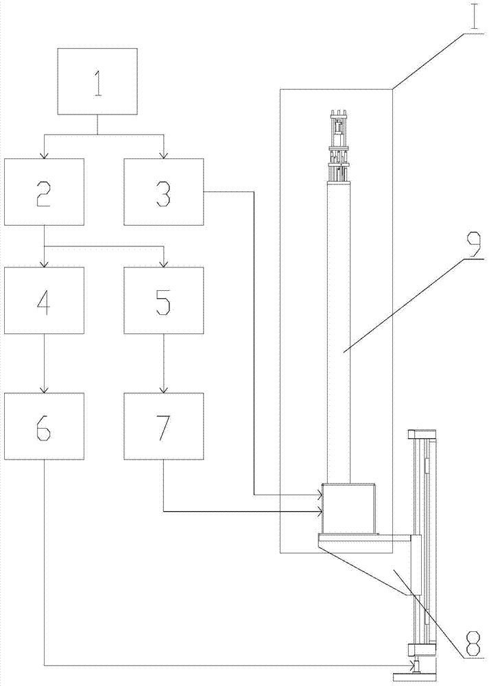
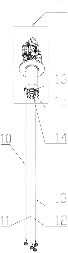
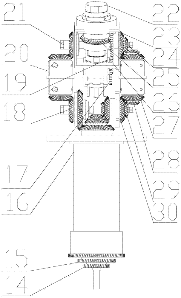
[0024] Such as Figure 1~3 As shown, the embodiment of the present invention is provided with a host computer 1, a PMAC controller 2, a spectrometer 3, an AC servo motor driver 4, four DC servo motor drivers 5, an AC servo motor 6, four DC servo motors 7, Edge magnetic field imaging plane lifting table 8, solid high-resolution imaging probe 9, sample chamber Y-axis motion system power transmission line 10, sample chamber rotary motion system power transmission line 11, sample chamber up and down motion system power transmission line 12, Sample chamber X-axis motion system power transmission line 13, sample chamber up and down motion system power transmission line 2 14, sample chamber X-axis motion system power transmission line 2 15, sample chamber Y-axis motion system power transmission line 2 16, sample chamber up and down Motion system power transmission line 7 1...


PUM


Abstract

The invention relates to a multi-dimensional nuclear magnetic resonance edge magnetic field imaging experimental device, which relates to nuclear magnetic resonance imaging. Equipped with upper computer, PMAC controller, spectrometer, AC servo motor driver, four DC servo motor drivers, AC servo motor, four DC servo motors, edge magnetic field imaging plane lifting platform, imaging probe, two sample chambers Y-axis movement System power transmission lines, five sample chamber rotary motion system power transmission lines, seven sample chamber up and down motion system power transmission lines, four sample chamber X-axis motion system power transmission lines, probe coils, sample chamber up and down motion system worm. It can realize arbitrary angle adjustment of the sample cavity, stable mechanical discontinuous rotation and relative movement between the sample cavity and the probe coil. Through the combination of positioning algorithm and precision mechanical structure, the movement of the sample cavity relative to the coil is realized, which solves the problem that the current international multi-dimensional edge magnetic field imaging probe experimental device cannot realize the imaging of large-scale samples under a super-strong gradient field.

Description

technical field [0001] The invention relates to nuclear magnetic resonance imaging, in particular to a multi-dimensional nuclear magnetic resonance edge magnetic field imaging experimental device. Background technique [0002] NMR fringe magnetic field imaging technology originated in the late 1980s. Compared with traditional NMR imaging technology, its remarkable feature is to use superconducting magnet edge super strong gradient field to image samples. The gradient field that can be generated by the gradient coils used in magnetic field equipment can generally only reach about 1.5T / m, which is much smaller than the 50-60T / m of the fringe magnetic field, and because the resolution of MRI is directly related to the gradient field strength, so in In terms of image resolution, fringe magnetic field imaging technology has greatly improved compared with traditional MRI technology. In the field of nuclear magnetic resonance imaging, since the molecules of solid samples cannot mo...

Claims


Application Information

Patent Timeline
Patent Type & Authority Patents(China)
IPC IPC(8): G01N24/08G01R33/48
Inventor 冯吴俊薛文东洪永强施建龙孙惠军陈忠
Owner XIAMEN UNIV
Why Eureka
Try Eureka