Image processing method and electronic device
An electronic device and image processing technology, applied in the field of image processing, can solve problems such as deformation of portraits and affecting user experience, and achieve the effect of avoiding severe distortion
- Summary
- Abstract
- Description
- Claims
- Application Information
AI Technical Summary
Problems solved by technology
Method used
Image
Examples
Embodiment 1
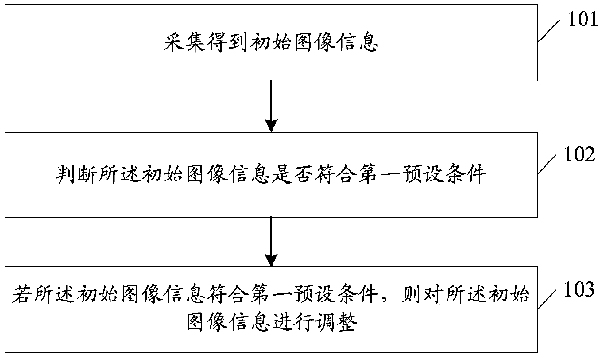
[0049] figure 1 It is a schematic flow chart of the image processing method in Embodiment 1 of the present invention. The image processing method in this example is applied to electronic equipment, such as figure 1 As shown, the image processing method includes the following steps:
[0050] Step 101, acquiring initial image information;
[0051] Here, the initial image information includes at least target object image information.
[0052] Specifically, when the electronic device scans and determines that a target object currently falls within the range of the image collection area, the initial image information may be collected by the collection unit in the electronic device. The collection unit may be a bottom camera in the electronic device.
[0053] Wherein, the image information of the target object is usually face image information; correspondingly, the initial image information is image information including at least a face image.
[0054] Step 102, judging whether ...
Embodiment 2
[0063] image 3 It is a schematic flow chart of the image processing method in Embodiment 2 of the present invention. The image processing method in this example is applied to electronic equipment, such as image 3 As shown, the image processing method includes the following steps:
[0064] Step 101, acquiring initial image information;
[0065] Here, the initial image information includes at least target object image information.
[0066] Specifically, when the electronic device scans and determines that a target object currently falls within the range of the image collection area, the initial image information may be collected by the collection unit in the electronic device. The collection unit may be a bottom camera in the electronic device.
[0067] Wherein, the image information of the target object is usually face image information; correspondingly, the initial image information is image information including at least a face image.
[0068] Step 1021, perform brightn...
Embodiment 3
[0079] Figure 4 It is a schematic flow chart of the image processing method in Embodiment 3 of the present invention. The image processing method in this example is applied to electronic equipment, such as Figure 4 As shown, the image processing method includes the following steps:
[0080] Step 101, acquiring initial image information;
[0081] Here, the initial image information includes at least target object image information.
[0082] Specifically, when the electronic device scans and determines that a target object currently falls within the range of the image collection area, the initial image information may be collected by the collection unit in the electronic device. The collection unit may be a bottom camera in the electronic device.
[0083] Wherein, the image information of the target object is usually face image information; correspondingly, the initial image information is image information including at least a face image.
[0084] Step 102, judging whethe...
PUM
 Abstract
Description
Claims
Application Information
 - R&D
- Intellectual Property
- Life Sciences
- Materials
- Tech Scout
- Unparalleled Data Quality
- Higher Quality Content
- 60% Fewer Hallucinations
Browse by: Latest US Patents, China's latest patents, Technical Efficacy Thesaurus, Application Domain, Technology Topic, Popular Technical Reports.
© 2025 PatSnap. All rights reserved.Legal|Privacy policy|Modern Slavery Act Transparency Statement|Sitemap|About US| Contact US: help@patsnap.com


