Piezoelectric resonator element and piezoelectric device

a piezoelectric device and resonator element technology, applied in the direction of generator/motor, instruments, surveying and navigation, etc., can solve the problems of easy oscillation not with the fundamental wave, difficult to change thickness t, etc., and achieve the effect of suppressing ci value and stabilizing flexural vibration

Inactive Publication Date: 2008-05-06
SEIKO EPSON CORP
View PDF13 Cites 47 Cited by
  • Summary
  • Abstract
  • Description
  • Claims
  • Application Information

AI Technical Summary

Benefits of technology

[0017]An advantage of some aspects of the invention is to provide a piezoelectric resonator element in which, in miniaturization of a tuning fork type resonator element, movement of resonating arms in an unnecessary direction is suppressed to thereby suppress the CI value and prevent deterioration of vibration characteristics, and a piezoelectric device utilizing such a piezoelectric resonator element.

Problems solved by technology

However, in processing the small piezoelectric resonator element 1, if the piezoelectric resonator element 1 is to be processed to have the small arm width w in particular while maintaining the characteristics of the element 1, the following difficulties arise.
Referring to FIG. 13, the thickness t is difficult to change since it is restricted by conditions of a material, such as a quartz wafer, to be processed.
Therefore, if a typical structure is used, many products suffer disadvantages that the CI value ratio, which is the ratio of the CI value of a harmonic wave to the CI value of the fundamental wave, is smaller than 1 as shown in FIG. 15 and thus oscillation easily arises not with the fundamental wave but with the second harmonic wave.

Method used


Image

  • Piezoelectric resonator element and piezoelectric device
  • Piezoelectric resonator element and piezoelectric device
  • Piezoelectric resonator element and piezoelectric device

Examples


Embodiment Construction

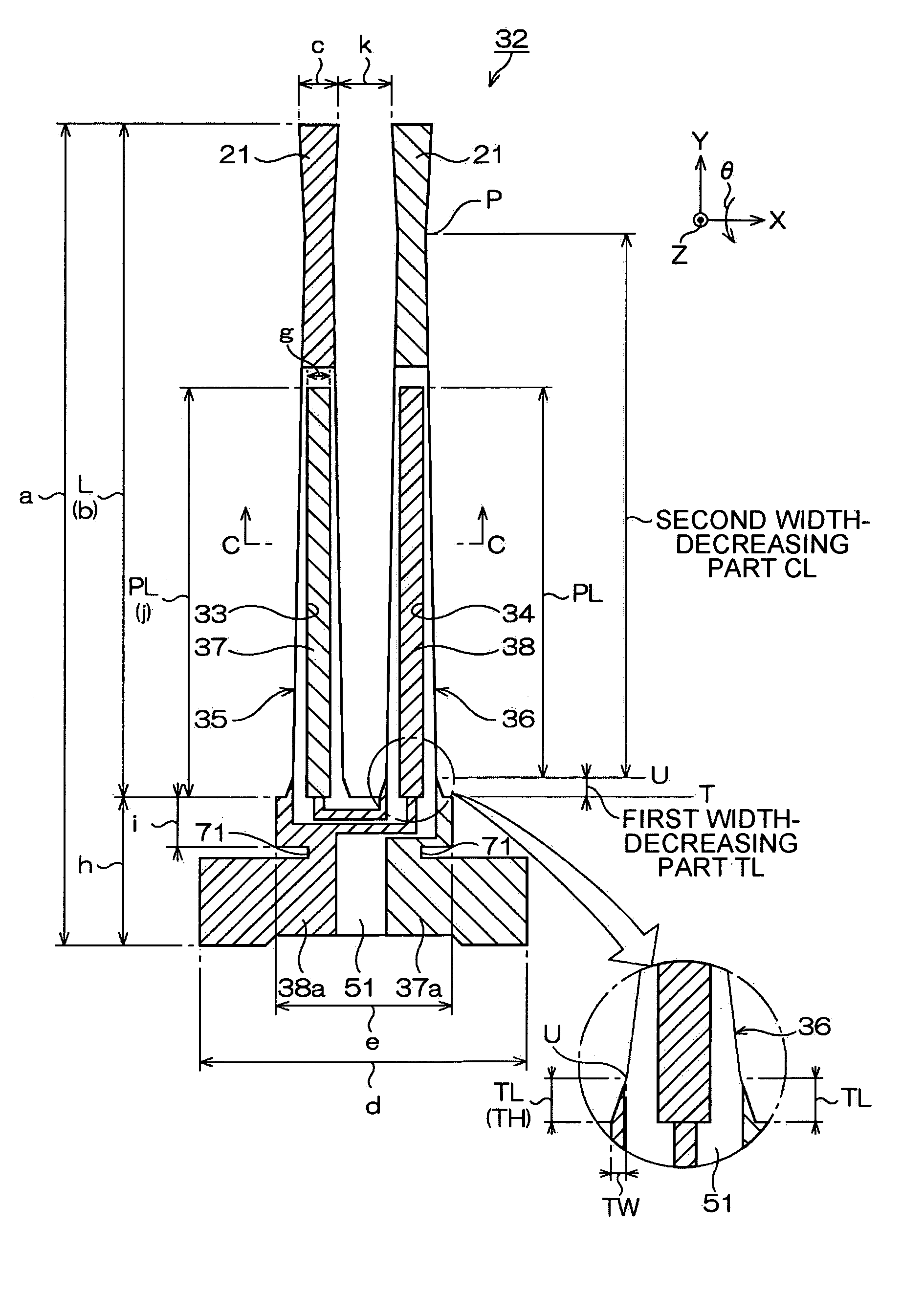
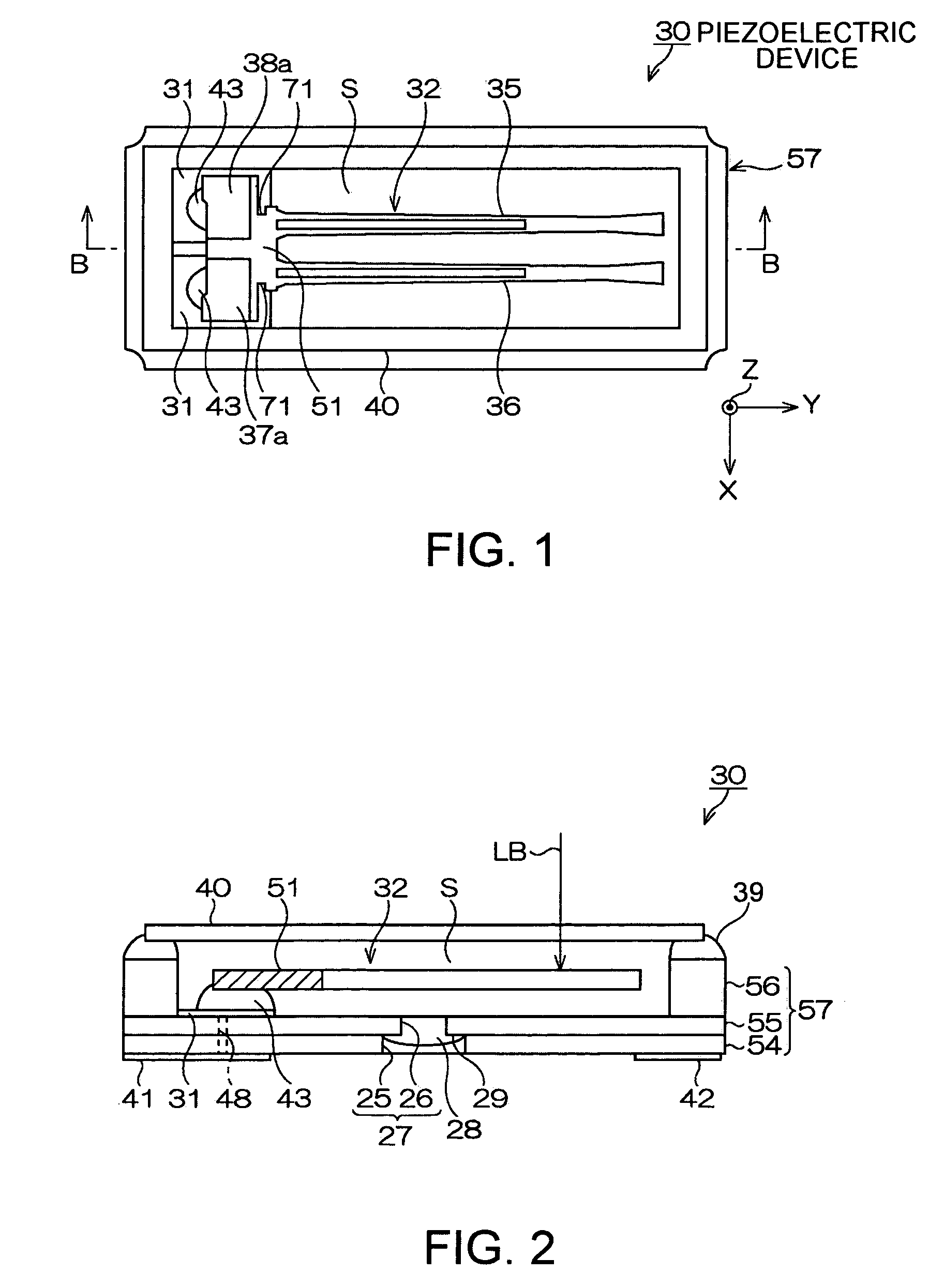
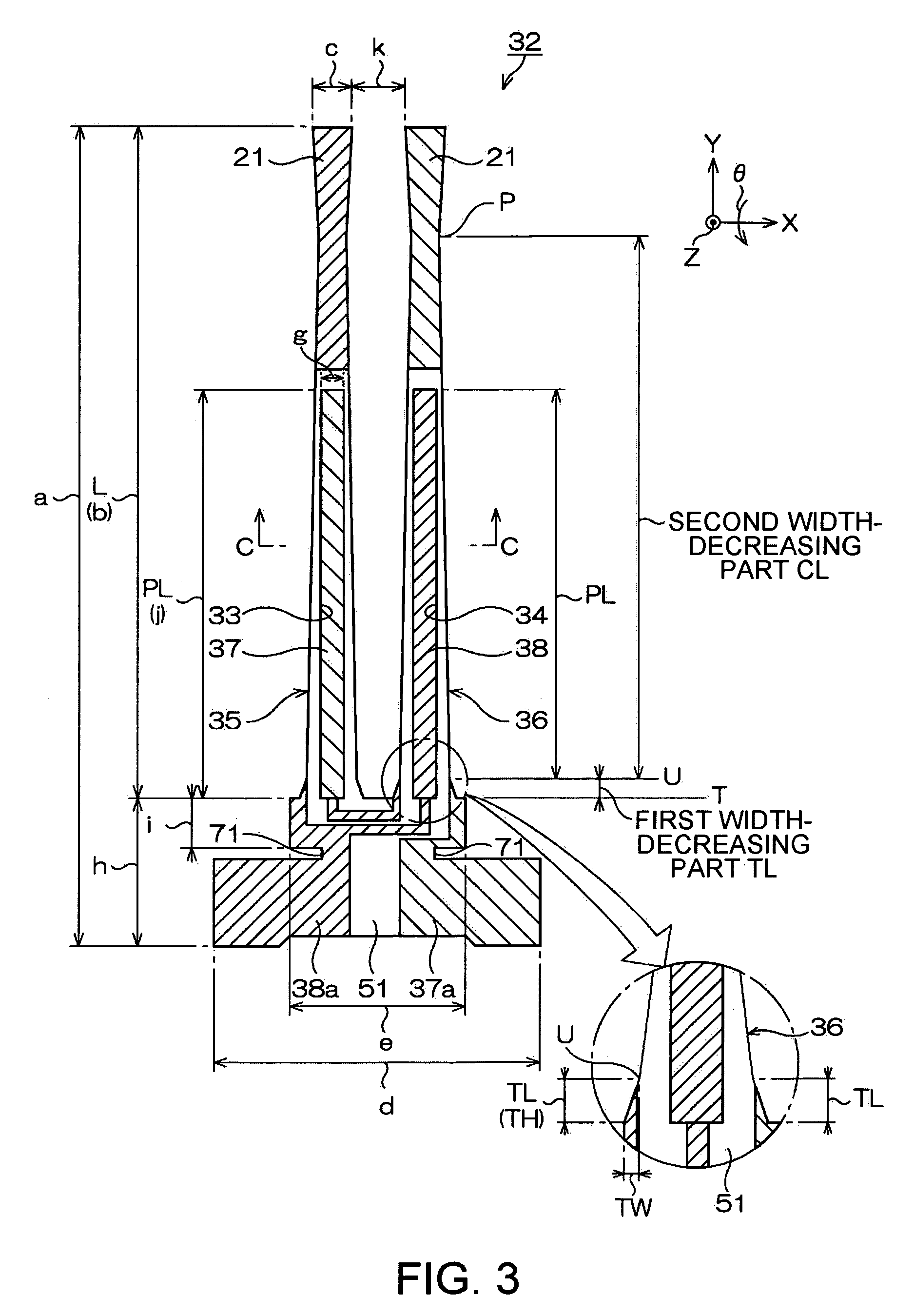
[0052]FIGS. 1 to 4 illustrate an embodiment of a piezoelectric device of the invention. FIG. 1 is a schematic plan view of the piezoelectric device. FIG. 2 is a schematic sectional view along the line B-B of FIG. 1. FIG. 3 is a schematic plan view illustrating an embodiment of a piezoelectric resonator element used in the piezoelectric device of FIG. 1. FIG. 4 is an end view cut along the line C-C of FIG. 3.

[0053]A package 57 is formed into a rectangular box shape for example as shown in FIGS. 1 and 2. Specifically, the package 57 is formed by stacking a first substrate 54, a second substrate 55 and a third substrate 56. For example, the package 57 is formed by forming a ceramic green sheet composed of aluminum oxide as an insulating material into the illustrated shape, and then sintering it.

[0054]The bottom of the package 57 has a through hole 27 for degassing in the manufacturing step. The through hole 27 is formed of a first hole 25 formed in the first substrate 54, and a second ...


PUM


Abstract

A piezoelectric resonator element includes a base portion formed of a piezoelectric material, a plurality of resonating arms formed integrally with the base portion and extending parallel to each other, a longitudinal groove formed along a longitudinal direction of each of the resonating arms, and an electrode for driving formed in the longitudinal groove. A width of each of the resonating arms is gradually decreased from the base portion toward a tip of the resonating arm, and a change point of width variation is provided close to the tip of the resonating arm. The width variation shifts from decrease to increase at the change point. The change point is located closer to the tip of the resonating arm than an end of the longitudinal groove.

Description

BACKGROUND[0001]1. Technical Field[0002]The present invention relates to improvements of a piezoelectric resonator element and a piezoelectric device housing a piezoelectric resonator element in a package or case.[0003]2. Related Art[0004]Piezoelectric devices, such as piezoelectric resonators and piezoelectric oscillators, have been widely used in small information apparatuses typified by HDDs (hard disk drives), mobile computers and IC cards, mobile communication apparatuses typified by cellular phones, car phones and paging systems, piezoelectric gyro sensors, and so on.[0005]FIG. 12 is a schematic plan view illustrating one example of piezoelectric resonator elements that have been typically used for piezoelectric devices. FIG. 13 is an end view cut along the line A-A of FIG. 12.[0006]Referring to the drawings, the outer shape of a piezoelectric resonator element 1 as a tuning fork type one is formed by etching a piezoelectric material such as quartz. The piezoelectric resonator...

Claims


Application Information

Patent Timeline
Patent Type & Authority Patents(United States)
IPC IPC(8): H03H9/21H03H9/215
CPCG01C19/5607H03H9/21H03H9/19H10N30/00
Inventor TANAYA, HIDEO
Owner SEIKO EPSON CORP
Why Eureka
Try Eureka