
Circuit and method for monitoring the integrity of a power supply

a power supply and integrity technology, applied in the direction of power supply for data processing, pulse automatic control, instruments, etc., can solve the problems of power abnormality and power abnormality

Active Publication Date: 2008-05-06
CYPRESS SEMICON CORP
View PDF15 Cites 7 Cited by
  • Summary
  • Abstract
  • Description
  • Claims
  • Application Information

AI Technical Summary

Benefits of technology

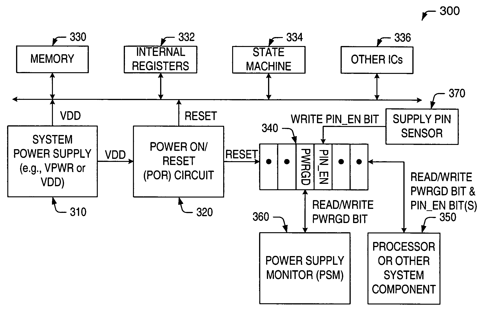
The patent text describes an improved circuit and method for monitoring the integrity of a power supply by monitoring the state of one or more bits stored within a status register. The circuit can detect changes in the state of the bits to determine if a power abnormality has occurred. The method includes setting a first bit in a status register if the power supply reaches a threshold level, setting a second bit in the register if the power supply pin is in electrical contact with the power supply, and monitoring the state of the first or second bit. The circuit can also include a status register for monitoring the integrity of an electrical connection between a first supply potential and a first supply pin. The technical effect of this invention is to provide a more reliable and efficient way to monitor the integrity of power supplies, which can help to prevent power abnormalities and improve the overall performance of the system.

Problems solved by technology

If the state of the first bit changes from a “set state” to a “cleared state,” the circuit designer or user of the system may conclude that a power abnormality has occurred, and that the abnormality is caused by the level of the power supply dropping below the threshold level.
If the second bit fails to be initially set, or changes from a “set state” to a “cleared state,” the circuit designer or user of the system may conclude that a power abnormality has occurred, due to loss of an electrical connection between the power supply pin and the power supply.

Method used


Image

  • Circuit and method for monitoring the integrity of a power supply
  • Circuit and method for monitoring the integrity of a power supply
  • Circuit and method for monitoring the integrity of a power supply

Examples


Embodiment Construction

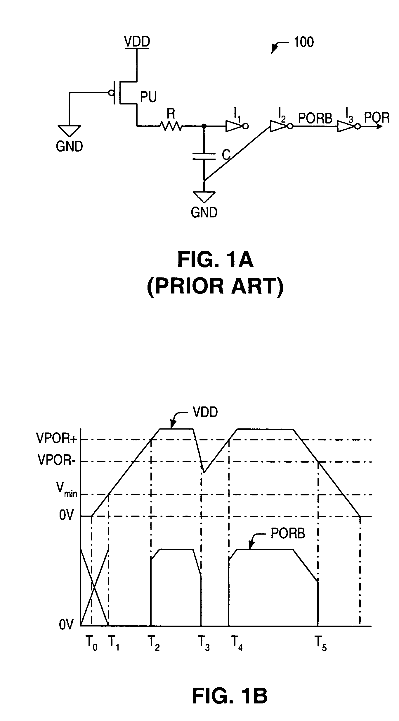
[0028]Turning now to the drawings, FIG. 1A illustrates one embodiment of a power-on reset (POR) circuit 100 that uses an RC structure to provide a reset signal to one or more system components based on a level of the power supply voltage (VDD). Essentially, as the power supply voltage ramps up to a predetermined level, the value of the reset signal (POR) on the output terminal of POR circuit 100 also rises, due to the increasing charge across capacitor C. When the charge across the capacitor is high enough, the stored charge drives the reset signal low (i.e., inactive) again.

[0029]The RC POR circuit of FIG. 1A includes a pull-up transistor (PU), a resistor (R), a capacitor (C), and inverters (I1, I2, I3). The number of inverters on the output path varies according to whether an active low or active high reset signal is desired. In some cases, an active low reset signal (PORB) may be supplied to one or more system components for performing a power-up or power-down reset sequence. In ...


PUM


Abstract

Circuits and methods are provided herein for monitoring the integrity of a power supply, the circuits and methods providing additional resources / information for diagnosing a cause behind a reset signal, and in some cases, a reason behind a power failure. A first method described herein provides exemplary steps for monitoring a level of a power supply voltage supplied to one or more system components. A second method describes exemplary steps for monitoring an electrical connection between the power supply (or ground supply) and one or more supply pins. Each of the methods involves monitoring a state of one or more bits stored, e.g., within a status register. The methods may be used separately, or in conjunction with one another, for detecting the occurrence of a power abnormality.

Description

BACKGROUND OF THE INVENTION[0001]1. Field of the Invention[0002]This invention relates to power supply monitoring schemes and, more particularly, to a circuit and method for monitoring the integrity of a power supply by monitoring a level of the power supply and / or an electrical connection between the power supply and a power supply pin.[0003]2. Description of the Related Art[0004]The following descriptions and examples are given as background only.[0005]Many integrated circuits and systems, such as microprocessors, microcontrollers and other programmable logic devices, are sensitive to the output levels of the power supplies driving the systems. In fact, such systems are often characterized by unique requirements for initialization control sequences, power-up and power-down control sequences, and unintentional reset sequences that may occur, e.g., during power glitches.[0006]For instance, many programmable logic devices (PLDs) must be “powered-up” or awakened from a zero power stat...

Claims


Application Information

Patent Timeline
Patent Type & Authority Patents(United States)
IPC IPC(8): H03L7/00
CPCG06F1/28G01R19/16552
Inventor LI, GABRIEL M.RICHMOND, GREG J.
Owner CYPRESS SEMICON CORP
Learn More