Supercharge Your Innovation With Domain-Expert AI Agents!

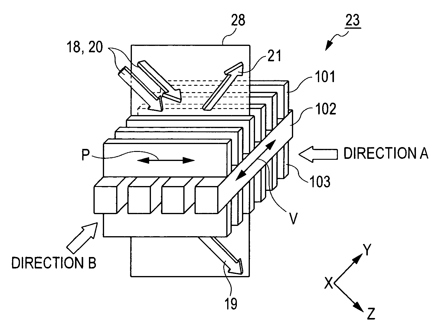
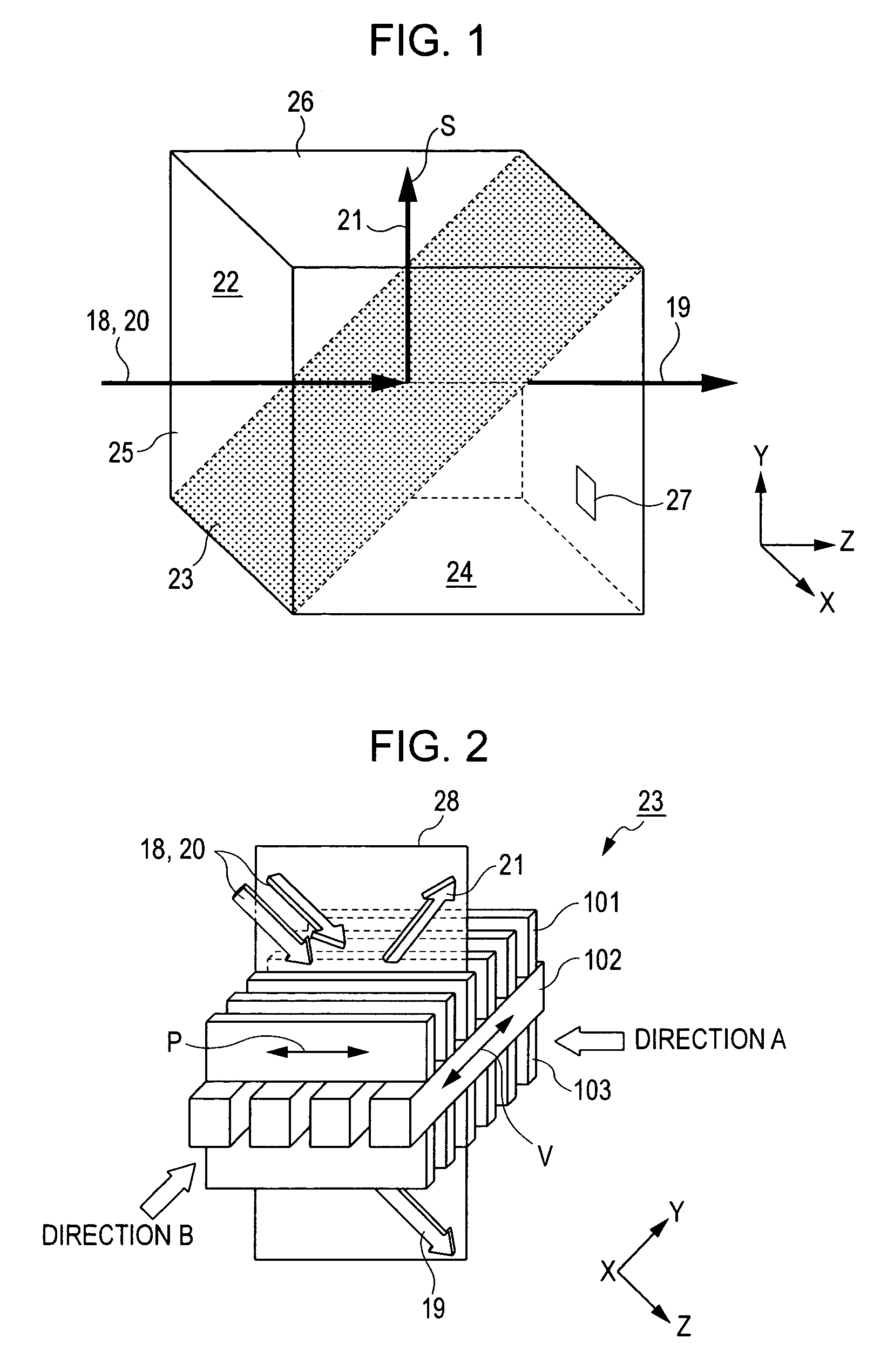
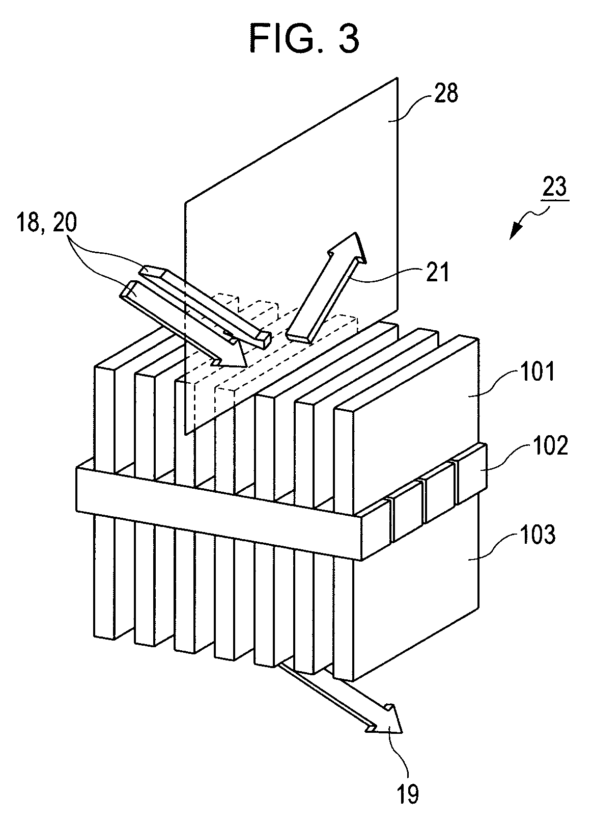
Polarizing beam splitter featuring stacked grating layers and display including the same

a technology of polarizing beam splitter and stacked grating, which is applied in the direction of polarizing elements, instruments, optics, etc., can solve the problems of insufficient optical performance of wire-grid polarizing beam splitter, inability to provide sufficient polarization splitting performance of materials that can be used in the production process, and inability to achieve sufficient optical performance. to achieve the effect of improving polarization splitting performan

Inactive Publication Date: 2008-05-06
CANON KK
View PDF10 Cites 12 Cited by
  • Summary
  • Abstract
  • Description
  • Claims
  • Application Information

AI Technical Summary

Benefits of technology

This patent is about a special optical device called a polarizing beam splitter that splits light into two different polarization directions. The device includes a layer that splits the light and a plate that helps to transmit the light. The special thing about this device is that it has a layer with a specific refractive index that helps to better split the light. By adjusting the refractive index of the layer and the plate, the device can perform its job better. This makes it easier to get high-quality light from the device.

Problems solved by technology

As a result, the plane-parallel plates become inclined in the optical path, thus causing astigmatism in the optical system.
On the other hand, the wire-grid polarizing beam splitter has difficulty in achieving sufficient optical performance because both reflected light and transmitted light undergo absorption.
Furthermore, materials that can be used in the production process can fail to provide sufficient polarization splitting performance.

Method used


Image

  • Polarizing beam splitter featuring stacked grating layers and display including the same
  • Polarizing beam splitter featuring stacked grating layers and display including the same
  • Polarizing beam splitter featuring stacked grating layers and display including the same

Examples


Embodiment Construction

[0033]The following description of exemplary embodiment(s) is / are merely illustrative in nature and is in no way intended to limit the invention, its application, or uses.

[0034]Processes, techniques, apparatus, and materials as known by one of ordinary skill in the art may not be discussed in detail but are intended to be part of the enabling description where appropriate. For example a light source is mentioned and an example of a high-pressure mercury vapor lamp can be used, however any light source that provides the illumination needed for the working of embodiments is intended to lie within the scope of exemplary embodiments.

[0035]Additionally the actual size of optical elements may not be discussed however any size from macro to nano sized optical elements are intended to lie within the scope of exemplary embodiments (e.g., waveplates with dimensions of nanometer size, micro size, centimeter size, and meter sizes). Additionally, exemplary embodiments are not limited to visual o...


PUM

PropertyMeasurementUnit
incident angleaaaaaaaaaa
angleaaaaaaaaaa
thicknessaaaaaaaaaa

Abstract

A polarizing beam splitter includes a polarization splitting layer which includes stacked one-dimensional grating layers. The grating layers can include alternating layers of at least one H layer having an effective refractive index nH for p-polarized light and at least one L layer having an effective refractive index nL for p-polarized light.

Description

BACKGROUND OF THE INVENTION[0001]1. Field of the Invention[0002]The present invention relates to polarizing beam splitters and displays including the polarizing beam splitters.[0003]2. Description of the Related Art[0004]Among known polarizing beam splitters is a wire-grid polarizing beam splitter, which includes a metal diffraction grid.[0005]This polarizing beam splitter includes conductors, for example metal conductors, arranged in parallel in a grid pattern. This structure has the effect of eliminating polarized light oscillating in a direction parallel to the grating and transmitting only polarized light oscillating in a direction substantially perpendicular to the grating. This polarizing beam splitter is intended for electromagnetic waves and infrared light, and has also been used for visible light.[0006]Because the wire grid has a sub-wavelength pitch, the polarizing beam splitter is produced by a semiconductor process (e.g., photolithography). Accordingly, the wire grid is ...

Claims


Application Information

Patent Timeline
Patent Type & Authority Patents(United States)
IPC IPC(8): G02F1/1335G02B5/30
CPCG02B5/3041G02B27/283
Inventor MOMOKI, KAZUHIKO
Owner CANON KK
Features
  • R&D
  • Intellectual Property
  • Life Sciences
  • Materials
  • Tech Scout
  • Unparalleled Data Quality
  • Higher Quality Content
  • 60% Fewer Hallucinations
Learn More