
Oxygen sensor

a sensor and oxygen technology, applied in the field of oxygen sensors, can solve the problems of affecting the exhaust efficiency, deteriorating fuel efficiency and power, and difficulty in sufficiently and adequately introducing the exhaust gas into the inside of the protector, and achieve the effect of not increasing the gas flow resistan

Inactive Publication Date: 2008-05-13
HITACHI LTD
View PDF4 Cites 5 Cited by
  • Summary
  • Abstract
  • Description
  • Claims
  • Application Information

AI Technical Summary

Benefits of technology

The present invention provides an oxygen sensor that can securely detect oxygen concentrations without increasing the resistance of the exhaust gas flow. This is achieved by setting the ratio of the outside diameter of the protector to the cross-sectional area of the flow passage in the pipe to be substantially smaller than or equal to 2.5%. This allows for a sufficient amount of exhaust gas to flow through the sensor without affecting the efficiency of the exhaust system. The invention also includes a set of guidelines for specific applications in motorcycles.

Problems solved by technology

Because of this, in a case where an amount of projection of the protector inside the exhaust pipe is large, this becomes resistance of exhaust gas flow and affects exhaust efficiency.
As a result, there is a possibility that this will lead to deteriorations in the fuel efficiency and power.
However, if the projection amount is small so as to reduce the resistance of exhaust gas flow, it becomes difficult to sufficiently and adequately introduce the exhaust gas into the inside of protector.

Method used


Image

  • Oxygen sensor
  • Oxygen sensor
  • Oxygen sensor

Examples


Embodiment Construction

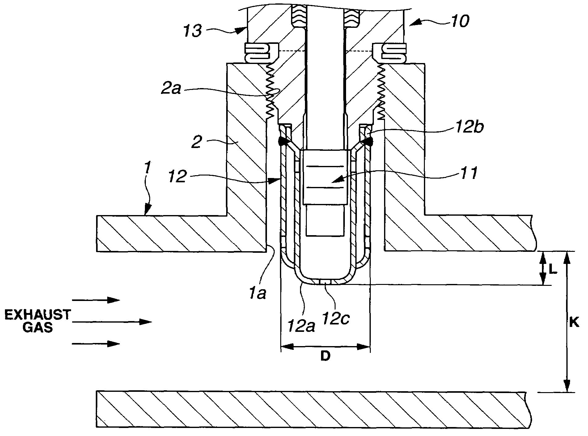
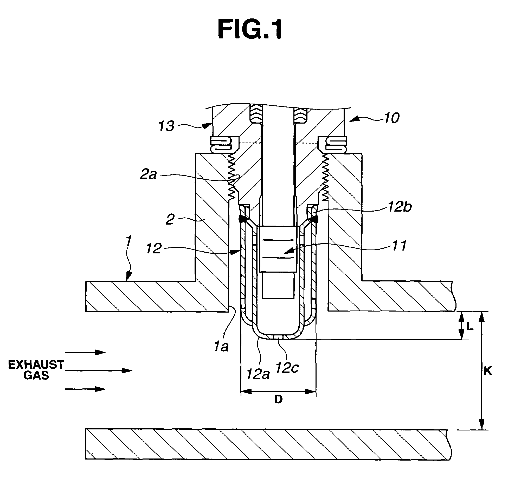
[0011]Embodiments of the present invention will be explained below with reference to the drawings. In the embodiments, an oxygen sensor that is used inside an exhaust pipe of internal combustion engine will be explained as one example (Thus, as a matter of course, the oxygen sensor can be used inside not only the exhaust pipe but also any pipe).

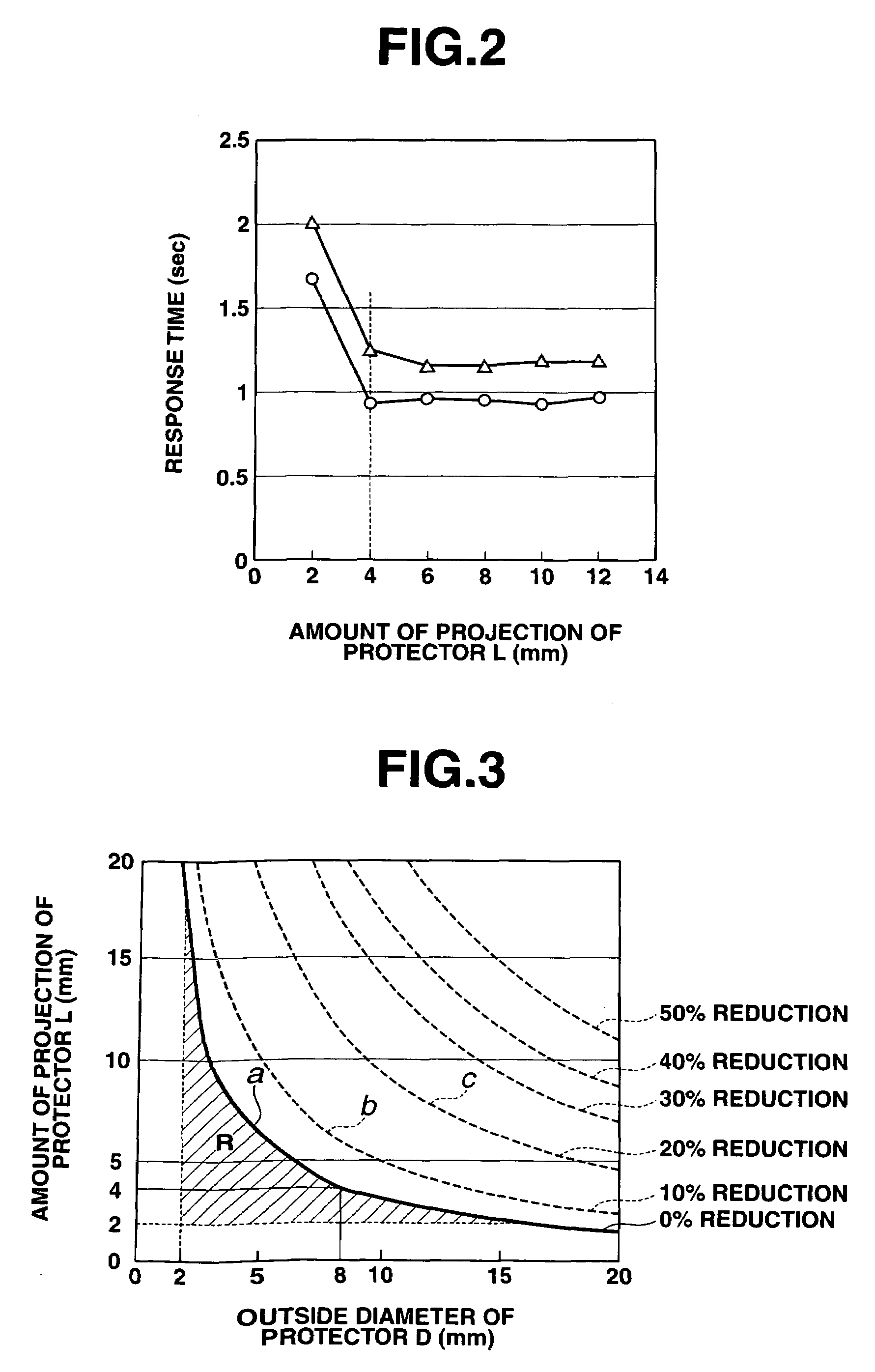
[0012]FIG. 1 is a sectional view of an oxygen sensor, under the state where the oxygen sensor is fixed to an exhaust pipe. FIG. 2 is a drawing to explain a relationship between an amount of projection of a protector and response time of the oxygen sensor. FIG. 3 is a drawing showing reduction curves of exhaust efficiency with respect to an outside diameter and the projection amount of the protector.

[0013]As shown in FIG. 1, a structure of an oxygen sensor 10 is mainly formed of a sensing element 11 which detects or senses oxygen concentrations in measurement exhaust gas that flows in an exhaust pipe 1, and a tubular or cylindrical shaped prot...


PUM


Abstract

An oxygen sensor includes a sensing element detecting an oxygen concentration in a measurement gas that flows in a pipe, a cylindrical protector which covers an outside of the sensing element and whose top end portion projects toward an inside of the pipe. An outside diameter D of the protector and a projection amount L of the protector inside the pipe are set so that a ratio of the product of the outside diameter D and the projection amount L (D×L) to a cross-sectional area S of a flow passage of the pipe becomes substantially smaller than or equal to 2.5%.

Description

BACKGROUND OF THE INVENTION[0001]The present invention relates to an oxygen sensor which detects oxygen concentrations in measurement gas that flows in a pipe.[0002]In recent years, there have been proposed and developed various oxygen sensors, and one oxygen sensor has been disclosed in Japanese Patent Provisional Publication No. 11-337513 (hereinafter is referred to as “JP11-337513”). In JP11-337513, an outside of a sensing element is covered with a protector, and this sensing element is inserted into an exhaust pipe with the sensing element covered in the protector. Then, these sensing element and protector are fixed to an inside of exhaust pipe such that exhaust gas flows into the protector from an inflow hole and touches the sensing element.SUMMARY OF THE INVENTION[0003]In the above oxygen sensor in JP11-337513, the exhaust gas contacts with the sensing element, and thereby electrically detecting the oxygen concentrations in the gas as a change of resistance value. However, in ...

Claims


Application Information

Patent Timeline
Patent Type & Authority Patents(United States)
IPC IPC(8): G01D21/00
CPCG01N27/4077
Inventor UCHIKAWA, AKIRAICHIYANAGI, FUTOSHITSUKADA, MASAO
Owner HITACHI LTD
Learn More