Sewing machine

a sewing machine and bobbin technology, applied in the field of sewing machines, can solve the problems of string material not being paid out at all, bobbins not rotating, extreme force required to rotate bobbins, etc., and achieve the effect of smooth payment, reducing tension and smooth string material paymen

Inactive Publication Date: 2008-05-13
TOKAI IND SEWING MACH CO LTD
View PDF12 Cites 5 Cited by
  • Summary
  • Abstract
  • Description
  • Claims
  • Application Information

AI Technical Summary

Benefits of technology

[0006]It is an object of the present invention to provide an improved sewing machine which allows a sewn material (string material) to be smoothly paid out from a bobbin even if the bobbin has an increased size so that an increased amount of sewn material (string material) can be wound thereon and the bobbin is heavy in weight.
[0008]According to the present invention, the tension detector detects the tension acting on the sewn material (e.g., string material) paid out from the rotary holder member (bobbin), the drive device drives the rotary holder member, and the driving operation of the drive device is controlled on the basis of the tension detection by the tension detector. Thus, when the sewn material (e.g., string material) is to be paid out from the rotary holder member (bobbin) and sewn onto the object of sewing (fabric), the drive device can be activated to drive or rotate the rotary holder member (bobbin) once the tension acting on the sewn material has increased due to the weight of the rotary holder member (bobbin) and other causes, which thereby allows the sewn material (e.g., string material) to be paid out smoothly. For example, once the sewn material (e.g., string material) has been paid out sufficiently to decrease the tension, the driving operation of the drive device is terminated to stop the paying-out of the string material. By positively rotating the bobbin in accordance with the tension acting on the string material in the aforementioned manner, the string material can be paid out smoothly, with the result that the string material can be sewn accurately and beautifully or aesthetically.
[0009]Further, according to the present invention, the rotary holder member (bobbin) having the sewn material (string material) wound thereon is positioned in a space above the needle bar. Thus, the invention is particularly useful in a case where the rotary holder member (bobbin) is constructed into a large size such that an increased amount of sewn material can be wound thereon. Namely, in the present invention, the rotary holder member (bobbin) is positively rotated by the drive device in accordance with the tension acting on the string material, and thus, even where the large-size rotary holder member (bobbin) is heavy in overall weight with a great amount of the sewn material (string material) wound thereon, the present invention achieves the superior benefit that the sewn material (string material) can be paid out appropriately and sewn onto the object of sewing accurately and beautifully.

Problems solved by technology

However, because the large-size bobbin having an increased amount of the string material wound thereon would have an increased overall weight, an extremely great force would be required to rotate the bobbin in order to pay out the string material.
Thus, if the bobbin is very heavy in weight, the rotation of the bobbin tends to be slow so that the paying-out of the string material is delayed behind the sewing operation, and the bobbin tends to start rotating rapidly so that the string material may be paid out more than necessary.
Further, depending on the weights of the bobbin and string material, the bobbin may fail to rotate even when it is pulled by the string material being sewn, in which case the string material may not be paid out at all.
Thus, the convention sewing machines would suffer from the inconveniences that the string material can not be paid out smoothly, the string material can not be sewn accurately and beautifully or aesthetically and the sewing of the string material is undesirably halted.

Method used


Image

  • Sewing machine
  • Sewing machine
  • Sewing machine

Examples


Embodiment Construction

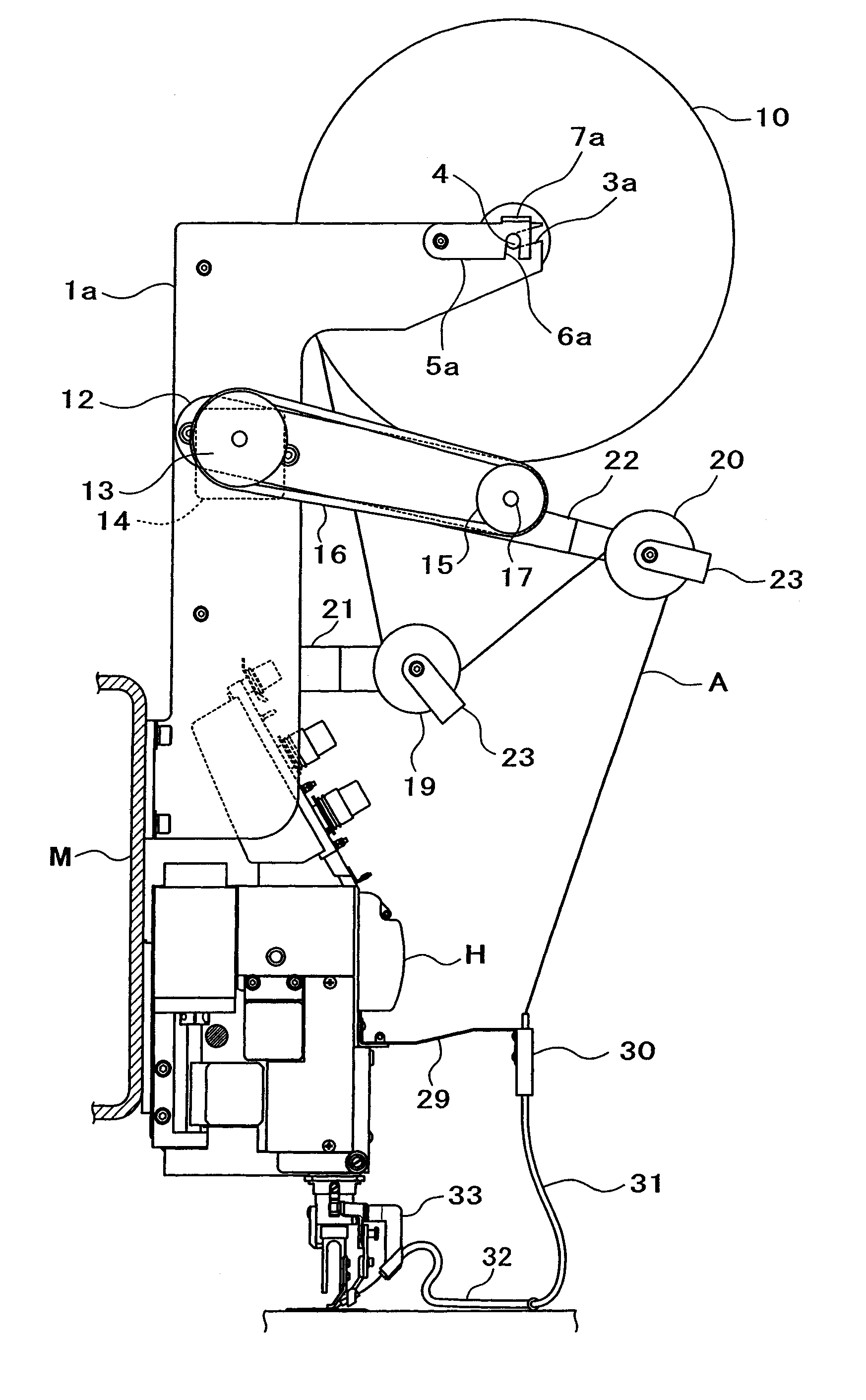
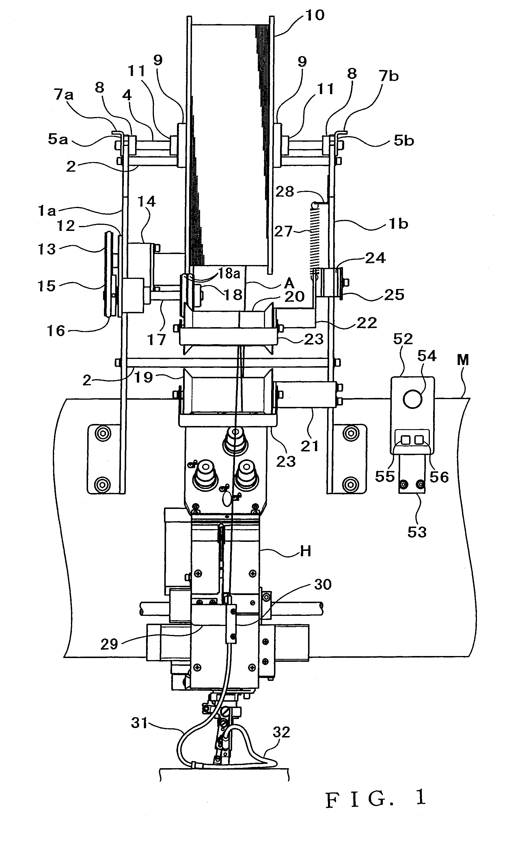
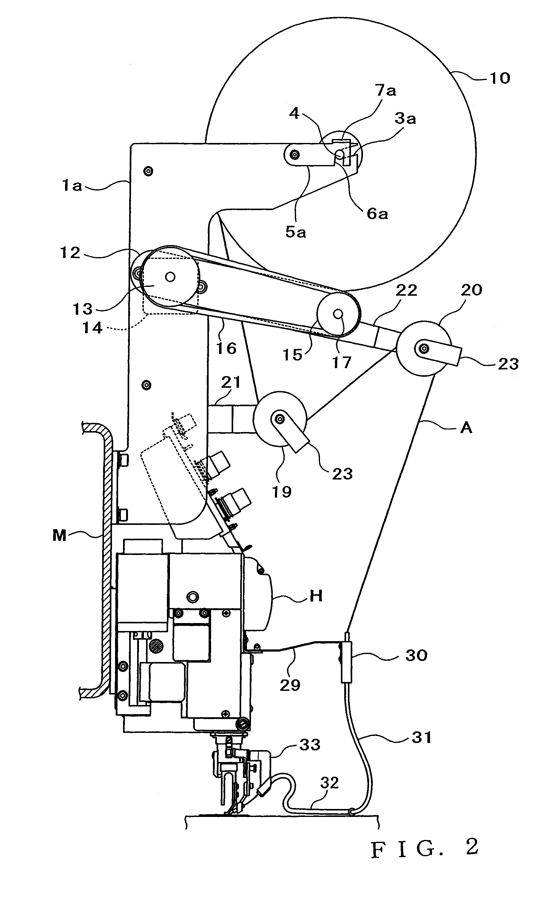
[0016]FIG. 1 is a front view showing an external appearance of part of an embroidering sewing machine of the present invention. FIG. 2 is a left side view of the embroidering sewing machine taken from a left side of the machine shown in FIG. 1. FIG. 3 is a right side view of the embroidering sewing machine taken from a right side of the machine shown in FIG. 1. Construction of the embroidering sewing machine will be described below with primary reference to FIGS. 1 to 3. Whereas a plurality of machine heads H are disposed at predetermined intervals on a front surface (i.e., a surface closer to a reader of FIG. 1, right side surface in FIG. 2, and left side surface in FIG. 3) of a machine frame M, only one of the machine heads H is shown in the figures to facilitate understanding of the following description. In addition to such machine heads H, a pair of support members 1a and 1b have respective one ends fixed, via bolts or the like, to predetermined left and right side positions of...


PUM


Abstract

Sewing machine includes a tension detection section (26) for detecting tension acting on a sewn material (A) paid out from a rotary holder member, and a drive section for driving the rotary holder member, and the driving operation of the drive section (14) is controlled on the basis of the detection by the tension detection section. Once the tension acting on the sewn material has increased, the rotary holder member is driven to rotate by the drive section, so that the sewn material can be paid out smoothly from the rotary holder member. The sewing machine is particularly useful in a case where the rotary holder member is constructed into an increased size so that an increased amount of the sewn material can be wound thereon.

Description

[0001]This application is a U. S. National Phase Application of PCT International Application PCT / JP2004 / 017013 filed on Nov. 16, 2004.TECHNICAL FIELD[0002]The present invention relates generally to sewing machines of a type which sews a string material, such as a tape or cord, to a fabric through lock switching. More particularly, the present invention relates to an improved sewing machine in which a bobbin having a string material wound thereon is disposed above a needle bar so that it can have an increased size, and which allows the string material to be smoothly paid out from the bobbin by positively rotating the bobbin as necessary when the string material is to be sewn to a fabric.BACKGROUND ART[0003]There have been known sewing machines of a type which includes a vertically driven needle bar, a sewing needle fixed to a lower end portion of the needle bar, a rotary member mounted concentrically with the needle bar and freely rotatable about the axis and a guide fixed to the ro...

Claims


Application Information

Patent Timeline
Patent Type & Authority Patents(United States)
IPC IPC(8): D05B69/02D05B53/00D05B35/06D05B27/00D05C7/08
CPCD05B35/06D05C7/08
Inventor TAJIMA, IKUOKONDOU, TETSUROU
Owner TOKAI IND SEWING MACH CO LTD
Why Eureka
Try Eureka