Formed body

a molding body and body technology, applied in the field of molding articles, can solve the problems of reducing the strength of bottles, unavoidably having seams at the joints, and virtually impossible to make the side walls stand at an angle of approximately 90° or more,

Inactive Publication Date: 2008-05-13
KAO CORP
View PDF51 Cites 54 Cited by
  • Summary
  • Abstract
  • Description
  • Claims
  • Application Information

AI Technical Summary

Benefits of technology

[0007]The present invention achieves the above object by providing a molded article made predominantly of pulp and comprising a bottom portion and a body portion, wherein the angle between the outer surface of a side wall of said body portion and the ground contact plane of said bottom portion is 85° or greater, the height of said body portion is 50 mm or more, and said molded article has corners whose thickness is greater than the thickness of other portions (hereinafter referred to as a first aspect).

Problems solved by technology

However, because plastic hollow containers involve various problems associated with waste disposal, hollow containers made of pulp are conceivable substitutes for plastic containers.
Because this container is produced by pressing a pulp layer deposited on a papermaking net with a pressing mold and then hot pressed in a metal mold, it is virtually impossible to make the side walls stand at an angle approximately 90° or more and to make the bottom deeper.
Since the bottle is made by separately forming a pulp layer on each of a pair of splits and then closing the splits to join the two pulp layers, it unavoidably has seams at the joint.
Such seams reduce the bottle strength and also impair the appearance.

Method used


Image

  • Formed body
  • Formed body
  • Formed body

Examples


first embodiment

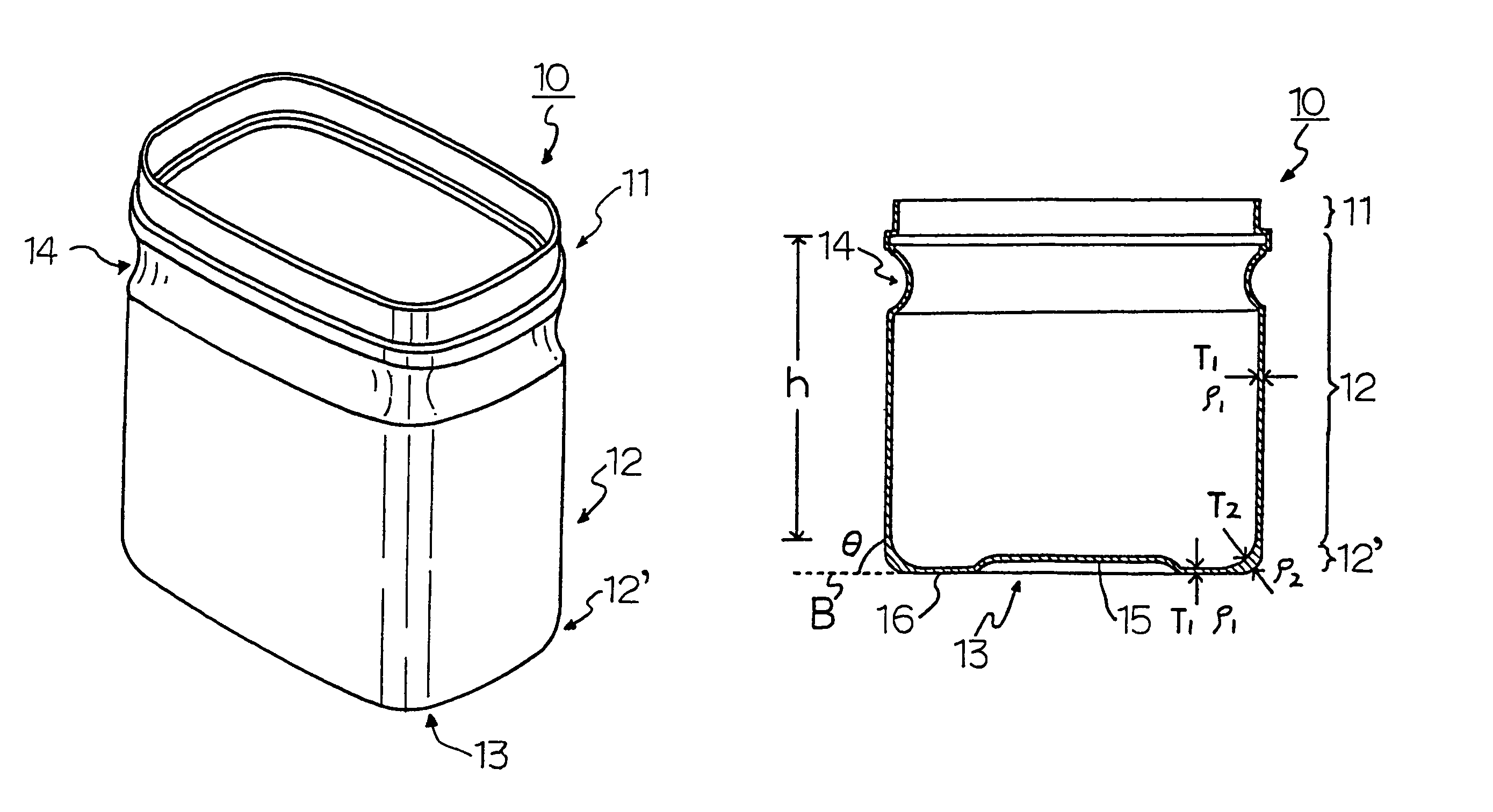
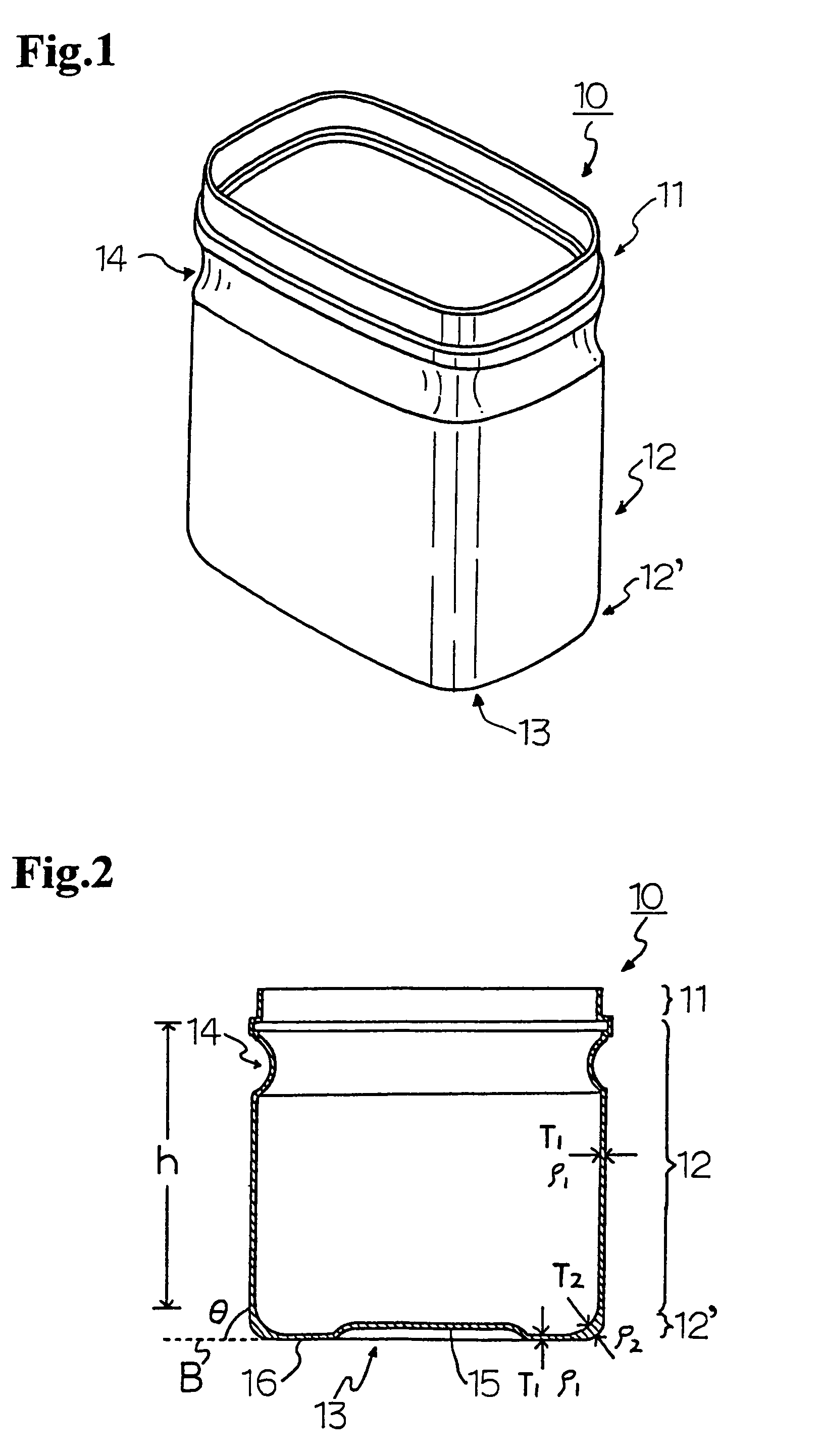
[0036]FIGS. 1 and 2 show a perspective and a vertical cross-section, respectively, of a molded article 10 according to the first aspect. The molded article 10 is a hollow container suitable for holding such contents as powder or granules. It has an opening portion 11 in the upper part, a body portion 12, and a bottom portion 13.

eighth embodiment

[0037]The body portion 12 and the bottom portion 13 connect by a curved portion 12′ to give the molded article 10 increased impact strength. The curvature of the curved portion 12′ is preferably 0.5 mm or more, particularly 5 mm or more, especially 7 mm or more, from the standpoint of improvements on impact strength, drying efficiency, surface finish, and adhesion to a plastic film that is used in the eighth embodiment hereinafter described. The transverse cross-section of the molded article 10 is a rectangle with its four corners rounded to give the molded article 10 increased impact strength. The curvature of the four corners is preferably 0.5 mm or more, particularly 5 mm or more, especially 7 mm or more, for the same reasons as described as for the curved portion 12′. The four sides of the rectangle are gently curved outward. The body portion 12 has a continuous depression 14 around its circumference to make the molded article 10 easy to hold. The depression 14 will be described...

second embodiment

[0068]As shown in FIGS. 7 and 8, a molded article of the second embodiment has a lid which swings to open and shut the opening portion 11. The lid and / or a measuring container are connected to the molded article 10 by integral molding via a first hinge and / or a second hinge which is / are thin and dense.

[0069]The lid 18, which is integrally molded with the molded article 10, links up with the molded article 10 near the opening portion 11 by the first hinge 31 so as to open and close the opening portion 11. The lid 18 consists of a flat top 32 and peripheral wall 33 standing upright from the peripheral edge of the top 32 so that the lower edge 33a of the peripheral wall 33 may be brought into, or out of, contact with the fitting part of the molded article 10. The lid 18 and the molded article 10 link up between the lower edge 33a of the peripheral wall 33 of the former and the horizontal contact part 25 of the latter.

[0070]The measuring container 19 is also integrally molded with the m...


PUM


Abstract

A molded article (10) made predominantly of pulp and comprising a bottom portion (13) and a body portion (12), wherein the angle θ between the outer surface of a side wall of the body portion (12) and the ground contact plane (B) of the bottom portion (13) is 85° or greater, and the height of the body portion (12) is 50 mm or more.

Description

TECHNICAL FIELD[0001]The present invention relates to a molded article comprising pulp as a major component.BACKGROUND ART[0002]Plastics are used as common materials of hollow containers, such as containers with a lid and bottles, for their excellent molding properties and productivity. However, because plastic hollow containers involve various problems associated with waste disposal, hollow containers made of pulp are conceivable substitutes for plastic containers. Pulp-made hollow containers are not only easy to dispose of but economical because they can be manufactured from used paper.[0003]Known techniques pertaining to pulp-made hollow containers include the technique disclosed in Japanese Patent Laid-Open No. 5-279998. The container disclosed has an angle of 45° or more at which the side walls rise and a depth of 15 mm or more. Because this container is produced by pressing a pulp layer deposited on a papermaking net with a pressing mold and then hot pressed in a metal mold, i...

Claims


Application Information

Patent Timeline
Patent Type & Authority Patents(United States)
IPC IPC(8): B65D1/00D21J3/10
CPCB65D1/0207B65D1/0215B65D1/12D21J7/00
Inventor OTANI, KENICHIKUMAMOTO, YOSHIAKISAGARA, KOICHIKODAMA, SHINJIGOTO, MINORUFUJINAMI, SUSUMUTSUURA, TOKUOOTAKURA, SHINJITOJO, TAKEHIKOSATO, YUKIYAISHIKAWA, MASATAKAODAJIMA, SHINGOTAKITA, MASANORI
Owner KAO CORP
Why Eureka
Try Eureka