Method and apparatus for balancing gas turbine engines

a gas turbine engine and assembly technology, applied in the field of gas turbine engines, can solve the problems of insufficient quantity of bolts available for weight attachment, insufficient quantity of bolts for weight attachment, and significant amount of unbalance correction of engines

Inactive Publication Date: 2008-05-13
GENERAL ELECTRIC CO
View PDF24 Cites 32 Cited by
  • Summary
  • Abstract
  • Description
  • Claims
  • Application Information

AI Technical Summary

Problems solved by technology

In use, at least one balance weight is coupled to the engine to facilitate reducing the vibrational forces on the surrounding vessel, whereas some engines may require a significant amount of unbalance correction.
However, coupling a plurality of balance weights to the engine results in a relatively time consuming process.
Accordingly, when the engine requires a significant amount of unbalance correction, there may be an insufficient quantity of bolts available for weight attachment.

Method used


Image

  • Method and apparatus for balancing gas turbine engines
  • Method and apparatus for balancing gas turbine engines
  • Method and apparatus for balancing gas turbine engines

Examples


Embodiment Construction

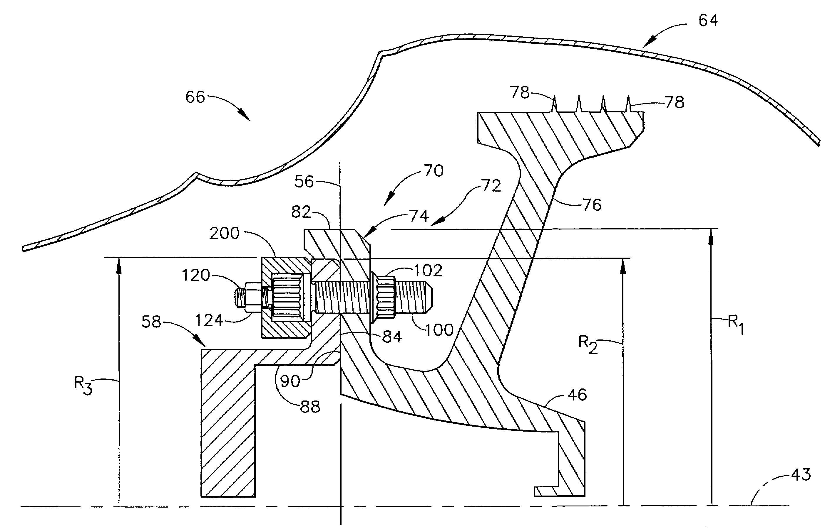
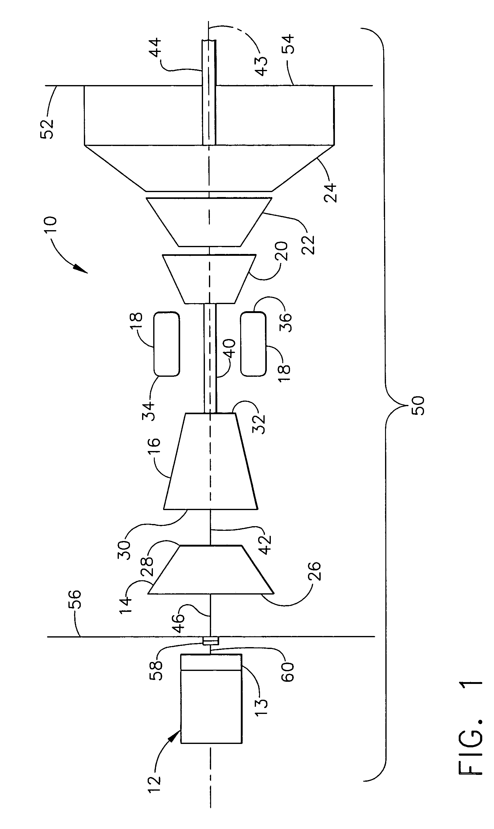
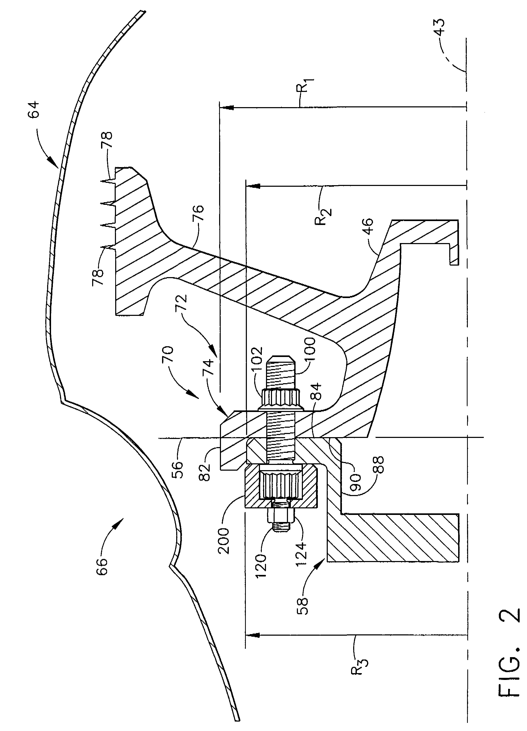
[0014]FIG. 1 is a block diagram of a gas turbine engine 10 in an installation wherein engine 10 is used to power a load such as an electric generator which is generally represented at 12. Generator 12 may be driven through a gearbox section 13. Hereinafter, references to generator 12 shall be understood to also include gearbox section 13. The engine 10 includes, in serial flow relationship, a low pressure compressor or booster 14, a high pressure compressor 16, a combustor 18, a high pressure turbine 20, a low pressure, or intermediate, turbine 22, and a power turbine 24. Low pressure compressor or booster 14 has an inlet 26 and an outlet 28. High pressure compressor 16 includes an inlet 30 and an outlet 32. Combustor 18 has an inlet 34 that is substantially coincident with high pressure compressor outlet 32, and an outlet 36. High pressure turbine 20 is coupled to high pressure compressor 16 with a first rotor shaft 40, and low pressure turbine 22 is coupled to low pressure compres...


PUM


Abstract

A method, system, and balanced rotating assembly are provided for field balancing an assembly including a power turbine. The method, system and assembly includes coupling the power turbine to a load, identifying a first balancing plane that is aft of the power turbine, and identifying a second balancing plane that is forward of the power turbine. A balancing correction is determined at each of the first and second balancing planes. A balance weight is mounted at the first balancing plane based on the balancing correction determined for the first balancing plane, and a balance weight is mounted at the second balancing plane based on the balancing correction determined for the second balancing plane, wherein each balance weight is coupled to at least two respective bolt head without removing the bolts.

Description

BACKGROUND OF THE INVENTION[0001]This invention relates generally to gas turbine engines, and more specifically to methods and apparatus for balancing an assembly that includes a gas turbine engine.[0002]At least some known gas turbine engines include, in serial flow arrangement, a compressor, a combustor, a high pressure turbine, and a low pressure turbine. The compressor, combustor and high pressure turbine are sometimes collectively referred to as the gas generator or core engine. Compressed air is channeled from the compressor to the combustor where it is mixed with fuel and ignited. The combustion gasses are channeled to the turbines which extract energy from the combustion gasses to power the compressors and to produce useful work to propel an aircraft in flight or to power a load, such as an electrical generator.[0003]Balancing turbine engines facilitates the avoidance of potentially destructive vibrational forces during engine operation. Balancing is achieved by rotating the...

Claims


Application Information

Patent Timeline
Patent Type & Authority Patents(United States)
IPC IPC(8): F01D25/04
CPCF01D5/027F01D25/243F16F15/32Y02T50/671Y10S416/50Y02T50/60
Inventor LEE, MICHAEL J.
Owner GENERAL ELECTRIC CO
Why Eureka
Try Eureka